Although I’m much more enamored with big motors, large drives, and prime movers, I’ve had my share of fun with smaller motors. One of the most memorable occasions was in a well-respected motor lab. There were a lot of smart, well-educated people standing around pontificating on how it would be mechanically impossible to make a clock spin backwards.
My coworker at the time was very familiar with the claw-pole type of synchronous machine in the clocks. We were actually working on a fair sized drive for a brushless dc (BLDC) machine in the lab. We discussed and concluded that all one had to do was dis-assemble the clock, flip the stator over on the claw-pole motor, and re-assemble the clock and plug it in. We further discussed the laminations and the likelihood of mechanical symmetry that would allow the flip and the possible wear on the gears that may cause cogging if they were to be spun the other direction.
When the smart people left, we took the clock down, spent two minutes doing our dirty work, and put the clock back up—to watch it spin backwards when we plugged it back into the ac source. We righted it at the end of the day, but the response from the superiors was noteworthy once they observed. “That couldn’t be done!”
From Clocks To Furnaces And Beyond
The first high-efficiency furnace I installed was on the order of 85% annual fuel utilization efficiency (AFUE). Looking at the insides, I was certain that was the end. A higher-efficiency unit “couldn’t be done.” The heat exchanger was compact, the exhaust temperature was fairly cool, and the size per BTU input was smaller than I’d imagined.
I recently upgraded to a 95% unit and marveled once again at the motors, drives, and controls that it took to get there. Just like the clock in the motor lab, it could be done with the right considerations. Every aspect of energy consumption in that unit has been squeezed, from the electronically controlled motor (ECM) in the blower to the fractional horsepower draft inducer motor.
In the world of small motors, comprehensive energy savings like the one mentioned above have pushed beyond simple machines. The draft inducers on combustion appliances like furnaces, heaters, and boilers have been prodded by increasing efficiency requirements to consider variable transfer rates. Variable transfer rates in a blower mean variable speed control.
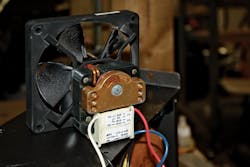
The fractional horsepower machines that used to turn off and on with relays and run at relatively fixed speed now have inverters in their highest-efficiency embodiments. Also, the tendency to use the “simplest machine,” perhaps a single-phase shaded pole or permanent split capacitor (PSC) machine, is shifting to more efficient solutions. This means that the shaded pole or PSC draft inducer motor is becoming a three-phase machine with its own drive (Fig. 1).
1. The shaded pole fan motor soon will be extinct, replaced by three-phase machines with their own drives.
This sort of thing is happening in many other applications. A lot of high-end residential and commercial refrigeration and dishwashing equipment is going down a similar path with more efficient fans, blowers, and pumps.
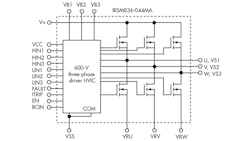
What then of the inverter product offering? When the various industries started adding drives to larger machines, the semiconductor world responded with various modules that were to be used as the power stage of the drive. These modules contained the three half-bridge converters or poles. Each pole had a high-side switch and a low-side switch. It also contained a high-voltage integrated circuit (HVIC) to drive the various switches accordingly.
These modules integrated many of the critical connection loops and nodes from an electromagnetic interference (EMI) standpoint. The also alleviated the need to scrutinize or adhere to all of the intermediate rules on creepage and clearance in those nodes, making the design of the inverter much easier and faster.
Inverter modules serve a wide variety of applications, from a few hundred watts to a couple kilowatts (Fig. 2). But what about the smaller motors? What of the machines in the 20-W to 200-W category? Most of the discrete insulated gate bipolar transistors (IGBTs) are too large for that application, as are the larger modules. They could be used, but they wouldn’t be economical since they would be very overkill for the application and the solution would be quite large.
2. This is what is inside of a typical inverter module—pretty tough to squeeze into a micro-inverter module, but it can be done.
We need some smaller switches and perhaps a lower-drive-current HVIC. They’re certainly available as discretes, but is it possible to make a “micro-inverter” module? Initially the path was much the same as the clock in the motor lab. There was a brilliant consensus that it couldn’t be done. Then packaging was reexamined and a plastic, quad-sided, flat, no-leads (PQFN) package was selected as the host.
The IR trade name for this is the uIPM or micro-inverter power module. It can support motor currents up to 750 mA rms per phase and is available with 250-V or 500-V switches (approximately a 145-W motor maximum) in a 12- by 12-mm package or an 8- by 9-mm package depending on selection.
How To Specify The Module
When it comes to specifying the micro-inverter module for your application, you should strongly consider using phase current as your primary guideline. From an outside standpoint, that seems odd. The motor was designed for a certain work output with a certain Ke. But from a different viewpoint, let’s look at the micro-inverter as an ac source.
Regardless of whether the power factor is unity or zero, the source has to deliver current to the load. That current flow causes conduction losses in the internal switches that are pulse-width modulating to deliver the outputs of that source. Assuming that the source is loss limited (the power dissipation limit of the PQFN package), there will be a maximal rms current per phase that will be allowable regardless of the power factor of the load or the work output. For a given motor family, these things are easily correlated to work output. But in broad strokes, it’s best to consider phase current when specifying the micro-inverter module.
Getting Heat Out Of The Module
When we have a surface-mount package that dissipates power, we have a couple of different ways to remove the heat from the package. The easiest method is to design the printed-circuit board (PCB) to remove the heat. To do this, we have to use the output traces and the dc bus traces.
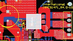
The output traces need to be thick and wide to carry the heat from the micro-inverter module, yet not so wide as to radiate electrostatic noise. The return can be quite large, as can the positive bus trace. The use of many smaller vias (10 to 15 mil ID) is encouraged to wick heat from the top of the PCB to the bottom. Additionally, a heatsink can be adhered to the top of the micro-inverter module with thermally conductive, electrically insulating tape or adhesive (Fig. 3).
3. This is a typical PCB layout for a micro-inverter module. Note the thick traces and extensive use of smaller vias to wick heat and not solder.
Additional Design Tips
A while back, I looked into some of the issues that you can have on the bench when designing modular inverters (see “A Few Brief Gate Drive Tricks Can Improve Your Design”). The math is clear. As efficiency is improved for a given piece of equipment, all aspects of power loss must be considered and ultimately improved upon.
I never thought I’d see the toasty little shaded pole motor heading toward obsolescence in small pumps or fans. But as we squeeze out more and more losses, it had to happen to get to “it can be done.” Historically, IR was the first to offer the larger inverter modules. Now, IR is the first to offer uIPM modules for small motor drives in a novel power quad flat-pack no-lead (PQFN) type package, which relies on the PCB copper for cooling.
When properly selected, the uIPM will provide a compact, efficient solution. I wonder how it would work as the output stage for a photovoltaic nanoinverter?
Paul Schimel is a senior applications engineer at International Rectifier. He has more than 17 years experience in power electronics design, EMC, and transformer design including offline ac-dc converters for medium and high power levels, motor drives, and dc-dc converters. He is a hands-on engineer and innovator, endlessly building power electronics circuitry, welding, and machining for audio, HVAC, and propulsion applications. Also, he is a licensed Professional Engineer and holds two patents.


