Recently while driving to work, I was thinking about the vast number of different applications in which electric motors are being controlled. From the seats, vent dampers, throttle bodies, and windows in my car to the diesel-electric locomotive running down the train tracks next to the highway, electric motors are truly everywhere. Arriving at my office, I rely on electric motors to open the parking garage gate, lift the elevator that carries me to my floor, and run the air conditioner that cools my office. Electric motors keep the world turning.
Related Articles
- What's The Difference Between Brush DC And Brushless DC Motors?
- Integrated Stepper Motor Driver Solutions Require Thermal Design Calculations
- SiGe BiCMOS Vs. CMOS For Signal Conditioning
High-efficiency motor control techniques from industrial applications now are being used in consumer applications (see “Industrial Energy-Efficiency Techniques Hit The Residential Market”). Some estimates place electric motor consumption at about 30% of all electrical energy produced in the world. As a result, there are huge incentives and pressures to improve the efficiency of electric motors in a wide variety of applications.
Required System Components
There is a wide variety of electric motor types covering an equally wide range of applications, including stepper, brushless dc, and ac induction motors. Stepper and brushless dc motors are often (but not always) used in lower-power applications such as appliances and machine tools, while ac induction motors tend to be used in higher-power applications such as pumps, fans, and industrial machine control. These ac motors can consume lots of power. A 1-hp motor draws about 750 W.
This file type includes high resolution graphics and schematics.
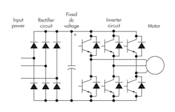
Many of the efforts for improving efficiency have targeted these larger ac induction motors, which rely on a varying ac current to create the rotating fields required to spin the motor. Controlling the speed of an ac induction motor requires changing the frequency of the ac waveform being fed into the motor windings. The ac frequency is adjusted typically by converting the ac line voltage into a dc voltage and then using a dc-ac inverter to create the desired ac frequency output (Fig. 1).
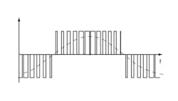
The most common technique for creating the ac waveform is to use a pulse-width modulation (PWM) signal to drive the output stage of the inverter. By varying the PWM waveform, we can create a variable frequency sine wave (Fig. 2). Implementation requires several application-critical high-voltage components. An ac induction motor has one to three phases depending on the number of motor windings. Each motor winding usually will have a driver on the high-voltage and low-voltage side of the winding.
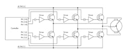
The actual control element for the current through the motor windings is a high-voltage transistor such as a power MOSFET or insulated gate bipolar transistor (IGBT). An isolated gate driver is required to drive these high-voltage transistors. This gate driver IC provides the necessary high current to turn on the transistor while isolating the low-voltage controller from damage (Fig. 3).
The transistors, particularly IGBTs, can require significant current into their gates to overcome the Miller capacitance, allowing the device to turn on. The higher the current, the more charge is delivered onto the Miller capacitance, enabling the transistor to turn on. While current drive is important, the ability of the gate drivers to precisely turn on and off also impacts the overall system efficiency.
When driving the motor phases, it often is important to not have the gate drivers overlap (i.e., turn on both the high-side and low-side transistors simultaneously), which could damage the transistors. To prevent overlap, each driver’s precise timing must be understood, and any variations between devices must be accounted for in the overall timing budget. If there is a large discrepancy in timing between different devices, both switches must be turned off for a longer period of time to account for it. This additional “dead time” reduces the system efficiency.
Traditional isolated gate drivers, which usually rely on optocouplers for isolation, suffer from slow switching times driven by the low speed of the optical isolation. The propagation delays of optically isolated gate drivers (or “opto-drivers”) can range from 200 ns to 700 ns compared to 5 ns for modern CMOS-based digital isolated gate drivers. The part-to-part variation of optical-based drivers can range from 350 ns to 500 ns versus 5 ns for CMOS-based drivers. All these timing delays and variations need to be accounted for in the overall system budget, which again will reduce system efficiency.
Looking Ahead
Many electric motor applications require long lifetimes of 10, 15, or even more than 20 years. The critical components in these motor control applications must be designed with this life expectancy in mind. Capacitors and the other isolation components often are the weakest link in the system. System lifetimes are improving with the use of modern CMOS-based isolation devices, though, which offer significantly longer working life than their optical-based counterparts since they aren’t subjected to LED wear-out.
As I prepare to head out of the office, I think about what additional electric motors I’ll encounter on my drive home. From the automatic doors at the supermarket to the garage door opener in my house, motor control applications occupy nearly every facet of our lives. Long live the electric motor!
Ross Sabolcik is the director of isolation products at Silicon Labs, providing strategic and product line marketing support for the company’s digital isolator, isolated gate driver, and current sensing products. He joined Silicon Labs in 1999 and has served as director for the company’s sub-gigahertz wireless products; director of applications and systems engineering for the company’s broadcast products; director of applications engineering for wireline products; and applications engineering manager for isolation products. Prior to Silicon Labs, he worked at National Instruments, managing product development for embedded DSP and MCU firmware, as well as board-level hardware design for precision PC instrumentation. He holds a master’s degree in computer and systems engineering from Rensselaer Polytechnic Institute and a BSEE from Penn State University. He can be reached at [email protected].
This file type includes high resolution graphics and schematics.


