Editor’s note: the author has provided LTspice files for the circuit that are posted below. Readers can use these files for simulation. (LTspice is a free application from Linear Technology Corp.) Microchip Technology, Analog Devices, and Freescale Semiconductor do not provide macro models that are usable with Spice, so the author has replaced them with behavioral and functional models in LTspice (Amodels and Dmodels). Also, the power supplies for the microcontroller (±2.5 V) can be implemented in many ways, so they are represented by “black boxes” referred to ground.
This idea shows the development of an ac-switch architecture, how it’s designed using MOS and bipolar discrete technologies, and several application circuits such as center-preserving dimmers, electronic transformers, self-resetting fuses, LED tube lights, and Christmas light controllers. To focus on the core concepts, it does not include line filtering, nor lightning or overvoltage protection.
Related Articles
- Free Downloadable Spice Tools Capture And Simulate Analog Circuits
- Triac And Diac Trigger Reside In The Same Package
- Dimmable LEDs Have A Bright Future
I hope that putting this in the public domain will stimulate other engineers to develop new circuits based on these concepts. One of the goals is to challenge the myth that relatively expensive optoisolators and relays are needed to do this job. In fact, it could be done with inexpensive, so called “vanilla” transistors. Another goal is to show that by having low voltages around the neutral line, very-high line voltages can be controlled. The mechanical wall switch handles 15 A. The intention is to have a replacement that is remotely controllable and capable of working over the Internet.
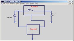
Figure 1 shows the general architecture of an ac switch and a controller that activates it. (For the netlist, click here.) Here, the “controller” is the human in traditional electromechanical switches. Note that the circuit preserves neutral ac line, with one end of the load at ground potential or very close to it. This discussion is initially restricted to resistive loads to understand the concepts. Later it will be extended to include reactive loads to show how switching can be done to avoid transients.
In Figure 2, the ac switch is in a center-preserving dimmer application.1 (For the netlist, click here.) The bottom half is implemented with PNP transistors and works only during the positive half of the input ac waveform, while the top half is implemented with NPN transistors and works only on the negative half cycle of the ac waveform.
The diodes in parallel with the switches help in the startup phase. The diodes in series with the control-current sources make sure that each half switch is operational only during its active half cycle. For 110-V applications, diodes and transistors with 250-V breakdown voltage are sufficient. The aim behind this switch is to arbitrarily apply the input-ac sine wave to the output load at times selected by the user.
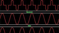
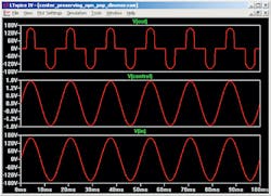
Figure 3 shows the three critical waveforms: input, control, and output. (For the simulation, click here.) The bipolar ac switch works well for loads up to 1 A. Beyond that, the low beta of the switch transistors results in a need for excessive control currents. In addition, switch losses start to become significant. However, you could replace the bipolar transistors with their MOS counterparts to overcome this problem.
Darlington combinations of MOS and bipolar devices allow for power-loss tradeoffs in the switch design. Such a dimmer is useful in applications involving compact fluorescent lamp (CFL) lighting, where the CFL circuit relies on the input peak-voltage value for its strike voltage. This would avoid the flickering that results when CFL bulbs are connected to the traditional SCR-Diac (diode for ac) dimmers. (Note that the available dimming range is unclear.)
In the generic microcontroller interface to this ac switch, the IC works from ±2.5 V and the drive three-state outputs are at 2.5, 0, and –2.5 V (Fig. 4). (For the netlist, click here.) Almost all standard microcontrollers can be used in this way, as long as they have a three-state output that could be tied to 0 V through a resistor.
Here, the switch is used to drive an LED tube light or a Christmas bulb string. A simple resistor is used to sense the current. This voltage is fed to the analog-to-digital port of the microcontroller, such as an Analog Devices ADUC848, Microchip Technology PIC16C77X, or Freescale Semiconductor MC9S08QD.
Instead of a simple resistor, you can use a current transformer or a Hall-effect device. (In Christmas light strings, this arrangement comes in handy when a bulb fuses out. Simply short it out with a paper-clip and the string is again working.) Since you are sensing the current and feeding it to the controller’s analog-to-digital converter, in the case of inductive loads, you can make sure the switch is turned off only when slewing di/dt current is going through zero. This will prevent transient spikes at the output and is useful when you are remotely controlling a three-speed motor, such as in a ceiling fan.
This simple electronic switch is intended to replace the ac mechanical switch. At this time, only a few vendors make sub-1-ΩRON high-voltage PMOS transistors. Although this design used an electronic dimmer as the example, this switch can be easily applied to lower ac voltages, remote control, and Internet applications. As in all non-isolated line applications, polarized connectors should be used to avoid reversing the line and neutral connections. As of 1962, the National Electrical Code (NEC) requires use of these connectors.
Acknowledgment
The author would like to acknowledge the help of D.G. Marsh, S.A. Dean, B.A. Wittman, and other anonymous editors for their help.
Reference
“Lighting Dimmers,” Rod Elliott, http://sound.westhost.com/lamps/dimmers.html
Apparajan Ganesan has an MS degree from the State University of New York (SUNY) at Stonybrook and has been designing circuits for 40 years. He has worked at companies including General Instrument, Bell Telephone Laboratories (Bell Labs), RCA, and Analog Devices and has been an independent consultant for the last 20 years. He can be reached at [email protected].


