Varistors, also called metal-oxide varistors (MOVs), are used to protect sensitive circuits from a variety of overvoltage conditions. Essentially, these voltage-dependent, nonlinear devices have electrical characteristics similar to back-to- back Zener diodes.
Download this article in .PDF format
Voltage TransientsVaristors feature high durability, which is essential for withstanding repeated high-peak pulse currents and high-energy surge transients. They also offer a wide voltage range, high energy absorption, and fast response to voltage transients. Peak current ratings range from 20 to 70,000 A, while peak energy ratings range from 0.01 to 10, 000 J.
In this context, “voltage transients” are defined as short-duration surges of electrical energy. In the electrical or electronic circuits that varistors intend to protect, this energy may be released either in a predictable manner via controlled switching actions, or randomly induced into a circuit from external sources. Common sources include:
• Lightning: In fact, transients induced by lightning are not the result of a direct strike. A lightning strike creates a magnetic field that can induce large magnitude transients in nearby electrical cables. A cloud-to-cloud strike can affect both overhead and buried cables. The outcome also is unpredictable—a strike that occurs a mile away can generate 70 V in electrical cables, and another can generate 10 kV from 160 yards away.
• Inductive-load switching: Generators, motors, relays, and transformers represent typical sources of inductive transients. Switching inductive loads on or off can generate high-energy transients that intensify in magnitude with increasingly heavy loads. When the inductive load is switched off, the collapsing magnetic field converts into electrical energy, which takes the form of a double exponential transient. Depending on the source, these transients can be as large as hundreds of volts and hundreds of amperes, with durations of 400 ms. Due to varying load sizes, there will be variance in wave shape, duration, peak current, and peak voltage of the transients. Once these variables are approximated, circuit designers will be able to select a suitable suppressor type.
• Electrostatic discharge (ESD): This energy is the result of an imbalance of positive and negative charges between objects. It’s characterized by very fast rise times and very high peak voltages and currents.
Varistor Basics
Varistors primarily consist of arrays of zinc-oxide (ZnO) balls, in which the ZnO was altered with small amounts of other metal oxides such as bismuth, cobalt, or manganese. In the MOV manufacturing process, these balls are sintered (fused) into a ceramic semiconductor. This produces a crystalline microstructure that allows these devices to dissipate very high levels of transient energy across their entire bulk. After sintering, the surface is metallized, and leads are attached via soldering.
Thanks to the MOVs’ high energy dissipation, they can be used to suppress lightning and other high-energy transients found in ac power-line applications. They’re equipped to withstand large amounts of energy and divert this potentially destructive energy away from sensitive electronics located downstream. MOVs, which are also used in dc circuits, come in a variety of form factors (Fig. 1).
Multilayer Varistors
Multilayer varistors (MLVs) address a specific part of the transient-voltage spectrum: the circuit-board environment. Although lower in energy, transients from ESD, inductive load switching, and even lightning-surge remnants might otherwise reach sensitive integrated circuits on the board. MLVs are also made of ZnO materials, but they’re fabricated with interwoven layers of metal electrodes and produced in leadless ceramic packages. They’re designed to transition from a high-impedance state to a conduction state when subjected to voltages that exceed their nominal voltage rating.
MLVs come in various chip form sizes, and are capable of dissipating significant surge energy for their size. Thus, they suit both data-line and power-supply transient-suppression applications.
Application Guidelines
When choosing an appropriate MOV for a specific overvoltage-protection application, the circuit designer must first determine the operating parameters of the circuit being protected, including:
• Circuit conditions such as the peak voltage and current during the surge event
• The MOV continuous operating voltage (should be at 20% above maximum system voltage under normal conditions)
• The number of surges the MOV must survive
• Acceptable let-through voltage for the protected circuit
• Any safety standards with which the circuit must comply
For the sake of simplicity in this example, assume the objective is to select a low-voltage dc disc MOV for the following circuit conditions and requirements:
• A 24-V dc circuit
• Current waveform for surge is 8 × 20 μs; voltage waveform is 1.2 × 50 μs (these are typical industry-standard waveforms)
• Peak current during the surge = 1000 A
• The MOV must be able to survive 40 surges
• Other circuit components (control IC, etc.) must be rated to withstand 300 V maximum
Step 1: To find the voltage rating of the MOV, allow for 20% headroom to account for voltage swell and power-supply tolerances: 24 V dc × 1.2 = 28.8 V dc. Given that no varistors have a voltage rating of exactly 28.8 V, check the datasheets for specifications for 31-V dc MOVs.
Step 2: To determine which MOV disc size to use, first identify the MOV series that minimally meet the 1000-A surge requirement. Inspecting the table above suggests a 20-mm MOV with a 31-V dc maximum continuous voltage rating (part number V20E25P) as a possible solution to meet the requirements.
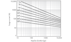
Step 3: Use the pulse-rating curves (Fig. 2) in the same datasheet to determine pulse capabilities relative to the 40 pulses at the 1000-A requirement.
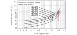
Step 4: Use the V-I curve (Fig. 3) in the MOV’s datasheet to verify that leak voltage will be less than the 300-V ceiling.
Protecting MOVs Against Thermal Runaway
The varistor’s absorption of the transient energy during a surge event produces localized heating within the component, which eventually leads to its degradation. If left unprotected, the degradation of a varistor can increase heating and thermal runaway. As such, a growing number of varistor-based surge-protection devices offer a built-in thermal disconnect function. It provides added protection from catastrophic failures and fire hazards, even under extreme circumstances of varistor end-of-life or sustained overvoltage.
MOVs are rated for specific ac-line operating voltages. Exceeding these limits by applying a sustained abnormal overvoltage condition could result in overheating and damage to the MOV.
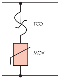
MOVs tend to degrade gradually after a large surge or multiple small surges. This degradation leads to increasing MOV leakage current; in turn, this raises the MOV’s temperature, even under normal conditions such as a 120-V ac or 240-V ac operating voltage. A thermal disconnect adjacent to the MOV (Fig. 4) can be used to sense the increase in MOV temperature while it continues to degrade to its end-of-life condition. At this point, the thermal disconnect will open the circuit, removing the degraded MOV from the circuit and thus preventing potential catastrophic failure.
LED Drivers and Lightning
Generally, most LED power supplies are a constant-current type, and are often referred to as LED drivers. These can be purchased as off-the-shelf assemblies containing MOVs to meet lower-level surge requirements.
Typically, drivers are rated to handle surges in the range of 1 to 4 kV. The varistor, ranging from 7 to 14 mm in diameter, is usually located downstream of the fuse on the ac mains. However, to provide higher-level surge immunity for lighting installed outdoors in exposed surge environments, outdoor-lighting OEMs may want to add surge-protection devices (SPDs) on the ac input lines of their luminaires ahead of the LED driver.
MOV Design Example: Industrial Motors
One aspect of ac motor protection is the surge-withstand capability of the motor itself. Paragraph 20.36.4 of the NEMA motor generator standard MG-1 defines a unit value of surge as:
u × VL-L (or 0.816 × VL-L)
where VL-L is the line-to-line voltage of the ac power system.
For transient rise times of 0.1 to 0.2 μs, twice the unit value of surge capability is required on stator windings. When rise times reach 1.2 μs or greater, 4.5 times the unit value is stipulated. In the case of external transients such as lightning, this would equate to a surge voltage capability of 918 VPEAK for a 230-V motor (full load current = 12 A) on a 250-V high-line condition. (Lightning surges can exceed these values, so stator windings would also need a suppression element for protection.)
Download this article in .PDF format
Operating temperatures are another consideration. Assume the ambient operating temperature for this application ranged from 0 to +70°C. This would be within the MOV’s -40 to +85°C rating, and there would be no requirement for derating of surge current or energy across this temperature range.Taking high-line tolerance into account, a 275-V ac-rated MOV may be chosen for this example. Using a 2-hp, single-phase, medium-sized motor, the MOV’s required surge-current rating would be determined by the peak current induced at the motor supply. Assuming a service location for the motor and a line impedance of 2 Ω, it was determined that a 3-kA lightning surge was possible.
In this case, one datasheet indicates a maximum clamping voltage of 3 kA at 900 V, which is below the 918-V suggested stator-winding withstand capability. If the motor’s operational life were estimated to be 20 years and specified as being able to withstand 80 lightning transients during term of service, the datasheet pulse-rating curves would verify a rating of 100+ surges.
For a more detailed explanation of how to match MOVs to applications, check out the “DC Application Varistor Design Guide.”


