Identify the Ideal Bench Power Supply by Asking the Right Questions
Although variable dc power supplies might appear to be relatively simple instruments, engineers rely on them to deliver stable, precise, and clean voltages and currents, regardless of the load. To pinpoint the appropriate bench power supply for a particular application, one must find answers to some important questions and understand how power supplies are specified.
Allot enough time early in the selection process to thoroughly consider the following power-supply questions—it will save substantial time and money later in the system configuration process.
How much power does the application require to energize the device under test (DUT)? What are the maximum voltage and current requirements?
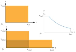
Different types of power supplies can have very different power envelopes (Figs. 1a, b, and c). In a highly versatile rectangular power envelope type of supply, any current can be supplied to the load at any voltage level. Another type has multiple rectangular envelopes for multiple ranges. The latter power envelope offers the option of higher values of one parameter at the expense of the other. For example, a supply with this type of envelope can output a higher level of current, but only at a lower maximum voltage.
Yet other supplies can deliver a hyperbolic envelope that provides a more continuous transition than multi-range power supplies. In this kind of supply, one parameter is inversely proportional to the other. High-power output supplies tend to have either a multi-range or a hyperbolic envelope. To make the right selection, take the time to evaluate the power levels required by the application.
How many outputs do I need?
Multi-output power supplies with high output accuracy have become more affordable, but it makes sense to ask which applications really demand them and those in which they’re not a necessity. In many cases, a single output is sufficient, but multi-output supplies can sometimes offer several important advantages:
• When creating a device that has digital and analog circuitry, or bipolar circuitry, a multi-output supply will be the more convenient power source. Triple-output power supplies typically contain two higher voltage outputs for analog circuits (to power multi-voltage circuits or to create bipolar power supplies for testing bipolar analog circuits) and a third output intended to power a digital circuit. Also, many triple-output power supplies maintain a fixed 5-V output for the third output source. If this voltage must be varied, or if the digital circuit is powered with a lower voltage, the third output cannot be used to power that circuit. Therefore, for the greatest flexibility, make sure that all three outputs are programmable.
• If the DUT requires individual isolated power-supply sections, it decision must be made: configure multiple isolated supplies (which can be expensive as well as inconvenient to operate) or buy a multi-output supply. The catch is that multi-output supplies can either have isolated outputs, or output channels tied to a common point on their low side. When the outputs connect to the same common point, they’re not suitable to power circuits that are isolated from each other.
• Digital board designs often include circuits that operate at different voltages. When testing these circuits with external power supplies, it’s important to power-up the circuits in the correct order to avoid stressing and damaging the low-voltage circuits. For applications that require powering circuits up and down in a specific sequence, a multi-output supply with independently controllable outputs is usually better than a set of individual supplies.
• For applications that require sourcing of more voltage or current beyond a single output’s capability, some multi-output power supplies allow outputs to be combined in series or in parallel. The catch is that a multi-output supply that has a positive and a negative output with their low connections tied together (non-isolated) cannot parallel the two outputs. To ensure flexibility, look for a multi-output power supply with isolated outputs.
• During circuit development, it’s essential to confirm that the circuit operates within its performance specifications over its defined voltage operating range. Multi-output supplies with tracking functionality offer a convenient way to test a bipolar circuit by linking both channels (positive-configured and negative-configured outputs) so that they change synchronously with each other.
This file type includes high resolution graphics and schematics when applicable.
What level of output accuracy is required?
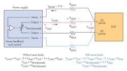
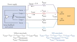
If tight control of voltage at the load is essential for research experimentation or device characterization, it’s important to review the power supply’s output accuracy and read-back specifications. Even that accuracy can be compromised if the supply controls the voltage at its output terminals. Feedback control at the DUT is essential; i.e., the supply should include sense connections (remote sensing) that can connect to the DUT where the power leads are also connected. (Fig. 2)
Bear in mind that lead wires separate power supply and load. The wires’ resistance, RLEAD, is determined by the length of the lead, the conductor material’s conductivity material, and the geometry of the conductor. Voltage at the load is:
VLOAD = VPROGRAMMED – 2 × VLEAD = VPROGRAMMED – 2 × ILOAD × RLEAD
If the load requires high current, then ILOAD is high, and VLEAD can easily be a few tenths of a volt, especially with long power-supply leads. A voltage at the load could easily be 80 to 160 mV lower than the desired voltage (with 2 to 4 A flowing through five feet of 0.004-â¦/ft., 16-gauge wire).
The remote-sensing technique solves the problem of voltage drop in the leads by extending the power-supply feedback loop to the input of the load. Two sense lines from the power supply connect to the DUT power inputs. These sense leads, which measure voltage, connect to a high-impedance voltage-measuring circuit in the power supply. Due to the circuit’s high input impedance, the voltage drop in the sense leads is negligible. The sense-lead voltage-measurement circuit becomes the feedback control loop for the power supply. The voltage at the load is fed back to the power supply by the sense leads. The power supply raises its output to overcome the voltage drop in the source leads and VLOAD = VPROGRAMMED. Therefore, the accuracy of the power supply can only be applied to the load via remote sensing.
What’s the maximum acceptable level of noise in the supply’s output?
If an application involves powering a very low-voltage circuit or a circuit that uses or measures very low currents, such as a transducer detector that must pick up millivolt or microampere signals, noise from external sources may cause problems.
One noise source is the power supply itself. This noise breaks down into two components: normal mode and common mode. Normal-mode noise, which is generated across the power supply’s output terminals, emanates from the power supply’s internal circuitry. Common-mode noise is earth-referenced noise originating from the powerline and stray capacitance across the main transformer.
Two types of bench dc power supplies are commonly used today—linear and switch-mode, or “switching.” Linear power supplies operate by rectifying ac line power to create dc, and then filtering and regulating it to produce user-selectable voltage or current levels. Linear supplies tend to be heavier because the 50- or 60-Hz transformer and associated filters are physically larger.
The linear topology generates a minimum of noise on the power supply’s output. Switch-mode supplies start out the same way, rectifying and filtering ac line input voltage. However, they chop (or “switch”) the dc into high-frequency ac, which is then converted into well-regulated dc.
The switching technique, due to its operation at kilohertz frequencies, makes it possible to use much smaller components in the input stage. Switch-mode power supplies are significantly smaller, lighter, and more efficient than linear power supplies, so they have replaced linear supplies for higher power requirements. On the negative side, their kilohertz switching frequency generates five to 10 times more noise than a linear supply. Whenever it’s imperative to minimize noise, choose a linear supply (if one is available) based on the power requirements.
What interfaces are needed?
Even for benchtop applications, remember that a power supply is just part of a larger interconnected system. Take the time to list the interface requirements (GPIB, USB, RS-232, RS-485, LAN, etc.) of every other piece of hardware. Will the system require a PC controller with which the supply must communicate? Is it necessary to control the power supply’s output using analog inputs? When long control lines or control lines exposed to an electrically noisy environment create signal-integrity concerns, isolated analog inputs can reduce or eliminate the susceptibility to signal degradation.
One other point to consider: Would a digital I/O interface make it easier to generate fault status outputs, or control an external relay or status lamp?
What about placement of output connectors?
Broadly speaking, front-panel connections, which simplify frequent access, are more common with supplies designed for benchtop use. Rear-panel connectors are generally considered superior for rack-based automated test systems—these rarely require changes after set up.
However, more manufacturers now offer power supplies equipped with both front- and rear-panel connections. This simplifies the transition from benchtop experimentation to high-speed automated test, because the same power supply suits both environments.
How should the supply be specified?
Although many key power-supply specifications will vary depending on the application, the following specs are critical in all cases:
Accuracy and Resolution
• Setting accuracy determines how close the regulated parameter is to its theoretical value as defined by an international standard. Output uncertainty in a power supply is largely due to error terms in of the digital-to-analog converter (DAC), including quantization error. Setting accuracy is tested by measuring the regulated variable with a traceable, precision measurement system connected to the output of the power supply. Setting accuracy is given as: ±(% of setting + offset)
• Setting resolution (sometimes called programming resolution) is the smallest change in voltage or current settings that can be selected on the power supply. The resolution specification limits the number of settable discrete levels. Often, this is defined by a combination of user-interface digits available and the number of bits in the DAC. A DAC with more bits has finer control of its output and can deliver more distinct values for the control loop to use as a reference. However, with corrections for offset and gain errors, there will be less resolution than the number of bits in the DAC would suggest. Setting resolution may be expressed as an absolute unit value or as a percentage of full scale.
• Readback accuracy determines how close the internally measured values are to the theoretical value of the output voltage (after setting accuracy is applied). It’s expressed as: ±(% of measured value + offset)
• Readback resolution is the smallest change in internally measured output voltage or current that discernible by the power supply. It’s usually expressed as an absolute value. but can also be given as a percentage of full scale.
Stability
Over the long term, a power supply’s performance inevitably changes due to aging. Maintaining long-term stability demands regular verification and calibration.
• Temperature stability: A power supply’s accuracy is usually specified as being valid over a particular temperature range, often between 20° and 30°C (68° to 86°F). When used in a stable ambient temperature environment, the effect of temperature on the output is usually minimal.
• Load regulation (voltage and current): Load regulation is a measure of the ability of an output channel to remain constant during changes in the load. As the impedance of the DUT changes, the regulated parameter should not change significantly.
Of course, if the load changes too much, the regulated (controlled) parameter may change between voltage (constant-voltage control) and current (constant-current control), depending on the limit setting for the unregulated parameter. Assuming the power supply doesn’t reach this crossover point, it maintains a low output impedance when operating as a voltage source, and a high output impedance when operating as a current source.
Load regulation may be specified in several ways. For example, voltage regulation can be expressed as voltage change per ampere drawn. However, most power-supply manufacturers express load regulation as output accuracy during a significant change in the unregulated parameter. This familiar format is easy to understand and verify through testing: ±(% of setting + offset).
• Line regulation (voltage and current): Line regulation is a measure of the power supply’s ability to maintain its output voltage or output current while ac line input voltage and frequency vary over the full allowable range. Line voltage and frequency greatly affect the available power to feed the output, especially when drawing maximum current from the supply.
Line regulation can be ignored in a lab with stable ac load voltage when testing for short periods. However, when working in an area prone to sags and swells in ac line voltage or when testing over extended periods, line regulation becomes an important consideration. Power-supply manufacturers usually express line regulation as an uncertainty in the output over the range of acceptable ac line parameters. This offers a worst-case picture, given as: ±(% of setting + offset)
AC characteristics
Direct-current power supplies don’t actually produce perfect dc outputs; there’s always some ac in the output. For some applications, high ac on the output can produce unexpected circuit behavior. In addition to ac noise, it may be useful to know the power supply’s transient response to changes in load and settings.
• Ripple and noise, spurious ac components on the output of a dc supply, are also often referred to as periodic and random deviation (PARD). These terms are often used interchangeably.
The term ripple refers to periodic ac on the output. When viewed in the frequency domain, ripple shows up as spurious responses. Unlike ripple, noise is random. Noise covers a broad spectrum, and when viewed in the frequency domain, manifests itself as an increase in the baseline.
PARD specifications must include a bandwidth and should be specified for both current and voltage. Current PARD becomes relevant when using a power supply in constant-current mode, and is often specified as an RMS value. Because the shape of PARD is indeterminate, voltage PARD will usually be expressed both as a root mean square voltage, which can provide a sense of the noise power, and as a peak-to-peak voltage, which may be relevant when driving high-impedance loads.
• Transient response is tested by applying significant step changes to load impedance and power-supply settings, and measuring the time to settle to a stable dc value. Most power supplies have a large capacitance in parallel with their outputs to help deliver clean, steady dc. Placing this capacitance in parallel with the load resistance results in a time constant; the size of the time constant varies with the load impedance. Due to the heavy dependence on the resistance of the load, response to setting changes must be specified for a specific load. It’s common to see specifications for open circuits, short circuits, or specific resistance values.
To learn more about choosing the right bench power supply for your application, download the Power Supply Selector Tool tablet app, downloadable from the iTunes store and Google play.
This file type includes high resolution graphics and schematics when applicable.
Robert Green, senior market development manager at Keithley Instruments (part of the Tektronix test and measurement portfolio), has been involved in the definition and introduction of a wide range of instrumentation. He holds a BS in electrical engineering from Cornell University and an MS in electrical engineering from Washington University, St. Louis, Mo.


