This file type includes high-resolution graphics and schematics when applicable.
As the world continues to connect at an incredibly rapid pace, advances in microprocessors have forced engineers to seek out solutions to increasingly complex power challenges at the board level. Lowering core voltages, tighter tolerances, rapidly rising power densities, and digital communication requirements all make the design engineer’s job much tougher.
This pressure is no more apparent than with point-of-load (POL) modules. This set of challenges has spawned several trends over the years, variously emphasizing performance, efficiency, reliability, size, and digital control in the solutions they produce. The power industry must now keep pace with ever-shrinking chip architectures and increasing on-board power requirements by providing high-current-density solutions at the point of load.
So, if you’re feeling the heat from the rapid pace of change and the requirements to meet upgraded standards for voltage, current, power, and switching speed, what should you look for in a POL module? Here are 10 points to bear in mind:
1. Input- and output-voltage range
One of the first things you need to identify in a potential POL-module solution is the input and output parameters. In your system, upstream from the POL, is a dc voltage rail that delivers power to the POL. Does the full range of that voltage rail (e.g., 12.0 V ±10%) fall within the input parameters of the POL? Downstream from the POL, you’re trying to deliver a clean voltage rail to your load. Does the POL output provide the necessary voltage range for your load (e.g., 0.9 V)?
2. Current capacity
Most POLs are identified by the maximum amount of current they can deliver to the load (e.g., 12 A, 60 A, 90 A). You will need to confirm that your nominal load plus any transients fall within the current capacity of the chosen POL. Drawing excess current beyond the rating of the POL may trip an overcurrent protection mechanism or thermally overload the POL.
3. Size
POL modules provide many advantages over “down” supplies, where the converter is piecemealed together on the main system board. One of the greatest advantages POL modules offer over down supplies is the smaller footprint they occupy on the main system board. While board space is often limited on the horizontal or X-Y plane, the vertical or Z axis is typically more accessible when space is required. Single in-line package (SIP) POL modules are growing in popularity due to increasing board densities and decreasing availability of horizontal real estate.
4. Voltage accuracy/tolerance
Many loads, like FPGAs, DSPs, and ASICs, continue to drive toward ever-smaller process nodes, demanding lower voltages and higher accuracies. It’s important to understand what initial set-point accuracy and tolerance your POL module must provide across various line (input voltage variations), load (nominal and transient output loading), and temperature conditions.
Transient loads are becoming an increasingly important part of the tolerance equation. Traditional analog POL topologies tend to be slower and fixed in their response to transient loads, often requiring larger amounts of output capacitors or a loosening of the voltage tolerance. Digital POL modules, however, often employ advanced algorithms, enabling them to respond with intelligence to the size and severity of various transient loads. This minimizes both the number of required output capacitors and minimizes the deviation of the output voltage due to the transient event.
5. Efficiency
Many different varieties of POL modules populate the industry, each with its own set of features and attributes. One often overlooked attribute is efficiency. Small amounts of inefficiency really start to add up. Choosing POL modules with higher efficiencies is not only good for the environment, but it positively impacts system reliability by reducing the heat expelled, thus lowering operating costs.
6. Current sharing
In higher-current applications, it may be advantageous to deploy multiple lower-current POL modules in a current-sharing configuration instead of designing in a single high-current POL module. Digitally controlled POL modules are particularly well-suited for this type of implementation, with the advantage being that the thermal load is spread across multiple modules instead of concentrated on a single POL.
With digitally controlled POL modules, you are often able to “phase spread” the modules. In other words, the switching cycle of each POL module is offset from one another, greatly improving the output-voltage ripple of the current-sharing group. In addition, in a current-sharing group, the POL modules are able to respond much more quickly to fast transients, improving the voltage accuracy of the output.
7. Communications
Many POL modules, including those from CUI, are now being developed with a digital communications interface, such as the common Inter-IC Communications (I2C) bus. Riding on top of the well-defined I2C physical layer, protocols such as the System Management Bus (SMBus) or the Power Management Bus (PMBus) are often utilized. This enables a system host controller to communicate with the POL using a common set of commands for configuration settings, control functions, and telemetry data.
8. Programmability
If your system requires multiple voltage rails, dynamic voltage rails, margining tests, etc., it makes sense to look for POL modules with programmability options. There are two basic types of programmability:
• The first, more simplistic version is known as pin-strapping. Pin-strapping allows you to place a resistor on your system board that the POL module will read upon startup. Depending on the value of that resistor, the POL module will configure itself to a specific output-voltage rail or configuration. Purchasing departments love this feature because you can buy just one POL module part number from the vendor, populate it in multiple locations on your system board (or on different projects all together), and generate many different voltage rails from the same sku. For example, one POL module could be pin-strapped to output 0.9 V, another to output 1.0 V, and yet another to output 1.35 V.
• As discussed above, more sophisticated POL modules offer a digital communications interface such as I2C, SMBus, or PMBus. This allows for a greater level of flexibility, since the host controller now has access to command, control, and telemetry features from the POL module. Using a set of pre-defined commands, the host controller can instruct the POL module when to turn on and turn off. It can also dynamically reconfigure the POL to support functions like voltage margining, power-saving modes, and modifying voltage/current/temperature protection. The host controller will often have access to telemetry data, too, such as temperature, input voltage, output voltage, and output current readings. Digital communication is also appreciated by design, manufacturing, and purchasing groups alike, in that a single POL part number can be placed all around the board and then configured via software to meet different voltage-rail needs.
9. Power density
Power density is a measure of the amount of power a POL module can deliver over the space that it occupies, typically expressed in watts per cubic inch (W/in.3) or watts per cubic centimeter (W/cm3). Today’s ever-more complex systems that require more power in the same or smaller space will seek out POL modules with higher power densities.
10. Less is more
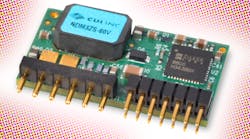
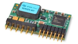
Another important aspect to consider when choosing a POL module: How much support circuitry is required to allow the POL to function in the way you want it to without running into layout and reliability challenges? In this regard, the edge goes to digitally controlled and compensated POL modules, such as CUI’s NDM3Z and NDM3ZS families (see the figure). Based on Intersil’s fully digital controllers featuring the company’s Charge Mode Control loop, they allow ultra-fast reactions to transient events (within a single switching cycle), minimizing the amount of capacitance required at the output. This helps minimize occupied board space, reduce costs, and improve reliability.


