This file type includes high-resolution graphics and schematics when applicable.
Power modules are very significant components for a MicroTCA system. They distribute the power and provide an interface to the MicroTCA Carrier Hub (MCH) for power management. Design specifications for power modules provide flexibility to power system designers that could impact the cost, performance, and reliability of a MicroTCA system.
MicroTCA belongs to the nine families of PCI Industrial Computers Manufacturers Group (PICMG) standards. MicroTCA was designed for building smaller systems than AdvancedTCA while retaining high availability architecture of AdvancedTCA. Let’s describe briefly the MicrotTCA standard and its background before taking a closer look of MicroTCA power modules.
MicroTCA
The Advanced Telecommunications Computing Architecture (ATCA, or AdvancedTCA) is a series of open-standard specifications developed by the PICMG in 2002. AdvancedTCA was designed to provide an open, multi-vendor architecture that would satisfy the requirements of the next generation of carrier-grade communications equipment.
The specifications provide enough information to allow board, backplane, and chassis vendors to independently develop products that will be interoperable when combined together. Details include board dimensions, equipment practice, connectors, power distribution, and robust system management architecture.
In 2005, the PICMG developed the Advanced Mezzanine Card (AMC) standard that defines the requirements for add-on modules to expand the functionality of an AdvancedTCA carrier board. These modules are also suitable for MicroTCA applications.
This standard, which provides a scaled version of AdvancedTCA for small-scale applications, was ratified by the PICMG in July 2006. Its focus is the latest generation of open-architecture platforms for information and communication technology (ICT) equipment. MicroTCA builds upon the heritage of previous architectures and technologies, specifically AdvancedTCA and AdvancedMC.
MicroTCA is suitable for applications that require lower power levels within an enclosure—customer-premises equipment (CPE), for example. Its main characteristics are modularity and scalability.
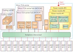
The MicroTCA system provides a mechanical and electrical platform for telecommunications and enterprise computer network equipment. As shown in Fig. 1, the principal components are:
• Between one and four power modules (PMs)
• Between one and two MicroTCA Carrier Hub (MCH) cards
• Between one and 12 Advanced Mezzanine Cards (AMCs)
• Between one and two cooling units (CUs)
• Mechanical resources needed to support all above elements
Power Modules for MicroTCA
The power module contains the majority of the power-conversion and control circuitry. It also eliminates the need for the large planar carrier-board of the AdvancedTCA systems.
Power modules are responsible for monitoring and protecting a MicroTCA system from power variations. A typical MicroTCA system supports one of the following power sources: -48 V dc, -60 V dc, +24 V dc, and Universal AC in the range of 100 to 240 V ac.
Conversion of the power input source to 12 and 3.3 V is done to provide payload power to each AMC and management power, respectively. Centralized MicroTCA power modules deliver higher power conversion density where some power modules can deliver up to 600 W.
Any given power module can be either primary or redundant; it cannot simultaneously serve both roles. One power module may deliver current to any load channel at any given time with the objective of limiting the maximum overcurrent possible for any channel. In the event of failure in any output channel of a primary power module, the redundant power module will take over responsibility for all of that primary power module’s output channels.
Power modules must be capable of supply payload and management power to up to two cooling units and two MicroTCA carrier hubs (MCHs). Therefore, power modules are designed to provide a total of 16 output power channels or 32 channels if payload and management power are considered separately.
Power modules also provide an interface to the MCH for power management. They can detect a new AMC and enable hot-swap support without affecting the rest of the system. Power management of the MicroTCA carrier has two distinct stages:
• The early power stage starts from the moment a source of energy is made available to the PM and ends when the carrier manager assumes control of power-management tasks.
• The normal power stage begins once a carrier manager is elected by one or more powered and initialized MCHs.
Autonomous mode may also be used during system maintenance—for example, when all MCHs are removed from a system but the remaining load modules must continue to operate undisturbed.
Applications
MicroTCA was originally intended for smaller telecom systems at the edge of the network. But it has moved into many non-telecom applications. Standardized, ruggedized versions are becoming popular in mobile, military, telemetry, data-acquisition, and avionics applications because MicroTCA offers an open bladed architecture that reduces size, weight, power, and cost.
Power Module: UTC011
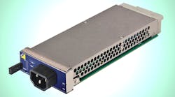
For example, VadaTech is a manufacturer of embedded boards, enabling software, and application-ready platforms that offers solutions for a range of markets including the military and aerospace market. One of its products is a single-module power module, the UTC011 (Fig. 2). The VadaTech UTC011 is a 241/460W power module for use in a MicroTCA air transport rack chassis.
The power module runs at 84% efficiency when running at maximum load, resulting in 200/400 W (available to the system). It is fully compliant with the MicroTCA.0 revision 1.0 specification, including dual-redundant I2C buses (IPMB-0).
Power Module: NAT-PM-AC600
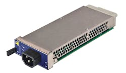
Networking, Automatization and Technology (N.A.T.) is a supplier for board and system level products based on AMC and MicroTCA. It offers the NAT-PM-AC600 power module, which is an example of a high-density and high-efficiency power module that could easily be used in applications such as medical, security, and industrial machine control (Fig. 3).
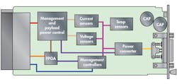
Supplying 600 W, it provides electrical support for the expected workload of 12 AMCs, two cooling units, and two MicroTCA carrier hubs. It supports redundancy as well as load sharing modes in accordance with the MicroTCA specifications. In case of an input power supply failure, the power for the onboard EMMC can be provided by SMP power from other power module. As a result, the MCH is able to analyze root cause failure (Fig. 4).
Conclusion
Power modules are critical to the success and reliability of a MicroTCA system, due to the amount of power functions that are centralized on them. There are many power modules in the market that comply with the MicroTCA family of specifications (MicroTCA.1, MicroTCA.2, MicroTCA.3, and MicroTCA.4). Depending on the applications, designers are able to apply the specifications and produce equipment with high efficiency, reasonable size, and modularity.
References:
Micro Telecommunications Computing Architecture, 2006
Ericcson, “Performance, cost, and reliability considerations in a MicroTCA power system”, 2007.
Ericcson, “Redundant MicroTCA Power systems”, 2008.
VadaTech, “ MicroTCA Overview”, 2014
PICMG Open Modular Computing Standards


