Electronics and automobiles have a long history together: Car radios started to appear in the 1930s, and the first electronic ignition was tested by Delco Remy in 1948. The pace picked up in the mid-1980s with the introduction of the first electronic engine-control units, and now electronic components comprise about 35% of the total cost of a vehicle.
Virtually everything electronic in a vehicle relies on the battery as the primary power source, and must, therefore, be protected against a range of battery-related mishaps. Reverse-polarity connection is one such event, which can occur upon installation of a new battery, reconnection of the original battery after repairs, or during a jump start.
To guard against potential disaster, all automotive electronic modules include circuitry to protect against reverse-polarity connections. In this article, we'll take a look at the most common circuits and their performance characteristics.
Standard Reverse-Polarity Tests
Electronic modules must pass a rigorous series of qualification tests in order to be approved for automotive use. The most common reverse-polarity test is specified by the ISO 16750-2 standard. For 12-V systems, the module must survive –14 V on the VBAT input for 60 seconds without damage. For 24-V systems, the test mandates –28 V for 60 seconds.
This is only part of the story, though. Even though the reverse-polarity circuitry isn't intended to protect against other types of overstress, it must also withstand the negative electrical pulses required by other standard tests such as ISO 7637-2, which governs conducted electrical transients. The ISO 7637-2 Test Pulse 1 simulates transients caused by the battery becoming disconnected from an inductive load and reaches –100 V. Test Pulse 3a simulates switching transients and extends to –150 V.
There are various options to protect downstream circuitry against reverse polarity.Of course, ISO isn’t the only standards organization. Japan has its JASO standards, and the major automotive manufacturers have their own qualification tests, but in most cases, they’re similar to the ISO standards.
Diode Protection
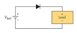
The simplest protection circuit is a diode in series with the battery (Fig. 1). As discussed earlier, the reverse breakdown voltage of a serial protection diode must be at least 150 V to meet ISO7637-2 requirements.
Under normal conditions, the diode is forward-biased. Under reverse battery conditions, the diode becomes reverse-biased and no current flows.
This approach is extremely simple, but suffers from two major disadvantages. A conventional diode has a forward voltage drop of 0.7 V, which reduces the voltage at the load. This could be an issue under certain conditions, such as cold cranking with a weak battery. In addition, the efficiency of any power circuitry downstream of the diode (e.g., a boost converter) suffers due to this drop.
To minimize these disadvantages, many designs use a Schottky diode, which has a lower forward-voltage drop than a standard diode, but is more expensive. The Schottky forward-voltage drop increases slightly with current; a typical automotive-grade device might give a power loss of 2% to 3%. If the power dissipation through a single diode is too high, several diodes may be connected in parallel.
MOSFET Protection
A MOSFET is a better alternative than a diode. The on-state forward voltage in a MOSFET depends on its rDS(ON), giving a voltage drop of rDS(ON) × ILOAD, which is much less than a Schottky diode.
The disadvantage is that a MOSFET is a 3-pin device and more expensive than a diode. In addition, an appropriate voltage must be applied to the gate to turn on the FET, which can be an issue depending on the FET and the circuit.
P-channel MOSFET Solution
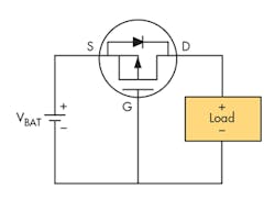
The simplest MOSFET option is to use a p-channel device in the battery line (Fig. 2). The benefit of using a p-channel MOSFET is that it doesn’t need a driver circuit. The PFET is turned on by applying a negative gate-to-source voltage (VGS). By connecting the gate pin to ground, the device is fully turned on when the battery is connected normally.
Like all MOSFETs, the PFET contains an intrinsic body diode that’s forward-biased in this configuration. When battery power is first applied, the intrinsic body diode will conduct until the channel switches on and shorts out the diode. Under a reverse-polarity condition, the body diode is reverse-biased and VGS will be positive, turning off the device.
P-channel devices are more efficient than n-channel devices, especially under conditions of high load current and low voltage, which often occur during start-stop or cold crank operation.
N-Channel MOSFET Solution
In a PFET, current flow is by means of holes instead of electrons. The mobility of a hole is around half that of an electron; therefore, an n-channel device will have half the rDS(ON) of an equivalent p-channel.
In other words, a PFET is around twice the size of an NFET to achieve the same impedance. Since cost is a function of die size, a PFET is also more expensive for similar capacity. A state-of-the-art NFET can achieve an rDS(ON) of around 3 mΩ, leading to power losses of 0.5% or less. On top of that, a wide variety of devices are available.
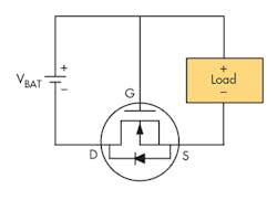
There are two ways to use an NFET in a reverse-polarity protection circuit. Most simply, it can be connected in the ground return path (Fig. 3). The operation is analogous to that of the PFET; since the gate is connected to the battery line, there’s no need for a driver circuit.
As before, a voltage of rDS(ON) × ILOAD is seen across the FET, raising the ground reference point for all internal circuits. This can be a problem, because many automotive sensors and switches use local grounds as their reference, which could cause a measurement error or malfunction.
To avoid this possibility and use the NFET in the battery line, a drive circuit must be added to raise the gate voltage above that of the battery and turn on the device.
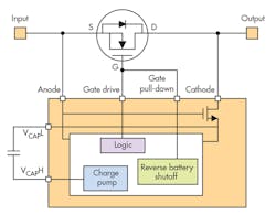
A discrete solution is an option, but it's often simpler to combine a discrete NFET with a specialized controller IC (Fig. 4). This combination emulates an ideal diode rectifier when connected in series with a power source. TI's LM74610-Q1 is one such device.
Adding discrete or integrated gate control increases complexity slightly, but offers superior performance compared to a PFET or Schottky diode. In high-power applications, it also eliminates the need for diode heat sinks or large thermal copper areas on the PCB.
During operation, the voltage across the MOSFET source and drain is constantly monitored by the controller's anode and cathode pins. An internal charge pump provides the gate drive for the external MOSFET, but is only turned on when it’s storing energy in the external charge pump capacitor VCAP. This stored energy is used to drive the gate of the MOSFET.
Forward conduction is primarily through the MOSFET. The body diode only conducts during charge-pump operation, approximately 2% of the time.
In any circuit where switching is used, EMI is a potential concern. In this application, though, the power being handled is very low, and the charge pump runs infrequently, minimizing generation of noise.
Conclusion
All electronic modules designed for automotive use must be equipped with circuits that protect against standard forms of electrical overstress. Reverse-polarity protection can be implemented with a number of simple circuits, and should be a routine part of any design.


