This file type includes high-resolution graphics and schematics when applicable.
The automotive industry perpetually introduces new features that enhance driver experience on top of existing popular systems such as infotainment and navigation systems, Bluetooth and USB connected-car functionality, high-performance LED lighting, and more. Now, advanced driver-assistance systems with features like collision avoidance and parking assist have also entered into the mix. This is in addition to established electronics systems like stereos, LCD displays, and critical basic control and power systems. Thus, it’s more important than ever to protect the circuitry of these advanced automotive electronics systems.
Furthermore, numerous mandatory safety systems require advanced electronic components. For example, in the EU, all new cars sold must incorporate direct tire-pressure monitoring systems (TPMS). The reliance on electronic technologies within the automotive sector has never been greater.
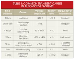
Many common transients in automotive systems have an impact on electronic-system performance (Table 1). They can be generated from a host of different sources, from common electrostatic discharges to disconnecting a battery.
Automotive designers of Infotainment, lighting, drive train, body, or chassis/safety groupings need to consider the circuit protection to combat these transients. Providing proper circuit protection helps ensure safety while reducing warranty and service-related costs for manufacturers.
ISO Requirements
Automotive electronic-systems design engineers should be aware of requirements set forth by the International Organization for Standardization (ISO). ISO 16750 applies to road vehicles, covering environmental conditions and testing for electrical and electronic equipment. Released in 2010, ISO 16750-2 was prepared by Technical Committee ISO/TC 22 to replace ISO 7637 for load dump (the pulse 5a and 5b portion). Further revisions to ISO 16750-2 were released in 2012.
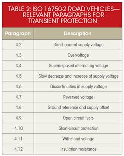
ISO 16750-2 applies to electric and electronic systems/components for road vehicles (Table 2). It describes potential environmental stresses and specifies tests and requirements for the specific mounting location on/in the road vehicle.
The Need for Load-Dump Protection
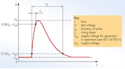
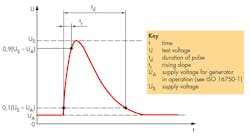
Within Paragraph 4.6, titled “Discontinuities in supply voltage,” is sub-section 4.6.4 Load Dump. A load dump occurs when the load to which a generator is delivering current is abruptly disconnected (Fig. 1). In automotive electronics, this applies to disconnecting a battery while it’s being charged by the alternator.
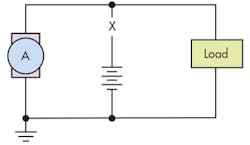
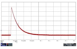
We can simulate a common occurrence of a load-dump transient (Fig. 2). This can happen if a discharged battery is disconnected while the alternator generates charging current with other loads remaining on the alternator circuit. Paragraph 4.6.4 is created for the simulation of the voltage surge produced by spinning alternators when the battery or some other significant load is accidentally disconnected.
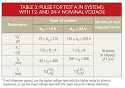
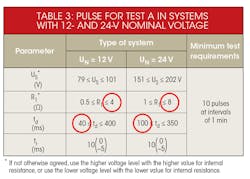
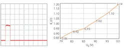
In Table 3, we can see the applied transient can be as high as 202 V and may take up to 400 ms to decay. Considering that series resistance could be 1 to 2 â¦, the surge current can be over 50 A for the 350-ms duration that design engineers need to consider for the system. The repetitive test of 10 pulses with one-minute intervals requires any load-dump protection solution to sustain the current handling. This includes needing to be able to reset with and without drift on resistance on the line.
Load-Dump Protection Options
Automotive designers can address circuit protection in several ways. First, there’s a switching solution. Here, a power supply might be designed to use a wide-input-range non-synchronous buck controller, which would offer automotive load-dump protection. It provides protection against load-dump transients by disconnecting the input supply to the controller or electronic subsystem for the specified duration of the pulse. It then reconnects with a fixed delay when conditions return to normal.
Such solutions have some limitations, though. The input operating ranges are known to function up to 75 V, acceptable for typical load-dump transients. But for transients above the controller’s upper operating range, the input supply needs to be disconnected. Other similar solutions require many discrete components and PCB real estate.
Another solution involves shunting. In this basic method of protecting an automotive electronic subsystem, the supply voltage at the ESA input is shunted with a semiconductor transient suppressor device.
The challenge for semiconductor industry in this scenario is to create a single transient-voltage-suppressor (TVS) device that can support higher 30- to 65-A surge currents (10 pulses every minute for 10 minutes). It also has to do this over the longer 350- to 400-ms pulse duration, as specified by the ISO 16750-2 standard.
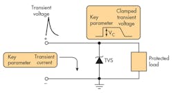
One possibility is a semiconductor silicon TVS diode, which contains a P/N junction similar to a Zener diode but with a larger cross-section that’s proportional to its surge power rating (Fig. 3). These diodes are clamping devices that limit voltage spikes by the low impedance avalanche breakdown of the P/N junction.
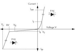
The electrical characteristic V-I curve shown in Figure 4 is similar to that of a Zener diode. However, TVS diodes are designed and characterized for transient voltage suppression, while Zener diodes are designed and specified for voltage regulation. With a TVS diode, an electrical transient is clamped instantaneously, diverting the applied surge current away from the protected device.
Automotive electronic designers typically select nominal resistance Ri values, from 2 ⦠for 12 V and 4 ⦠for 24-V systems (Table 3 again, but with selected values in red circles). They also select reduced td duration, from 40 ms for 12 V and 100 ms for 24-V systems. These are chosen to minimize surge current during load-dump transients.
Automotive designers often use lower-surge-rated—1.5 or 3 kW—TVS diode devices in load-dump protection circuits. But, is this load dump protection robust enough for current usage conditions, considering the ever-growing amount of electronic systems in automotive vehicles?
At a minimum, automotive designers need to implement circuit protection that meets ISO 16750-2 and AEC-Q101 reliability standards. However, with today’s electronics systems, designers can gain better assurance against costly warranty, repair, and other liabilities by exceeding these standard requirements. Basic circuit-protection capabilities should include solutions that provide a very low clamping voltage, RoHS and REACH compliance, and more.
Coupled with the need to increase circuit protection is the need to reduce costs. Of course, then, a circuit-protection solution that aids in controlling manufacturing costs and PCB real-estate savings becomes a big plus. Manufacturers need also be concerned with reducing lead times related to sourcing devices.
Figure 5 illustrates an applied ISO-16750-2 load-dump input waveform. Figures 6, 7, and 8 show examples of load-dump protection performance at 14 V, 22 V, and 33 V, respectively, for 12- and 24-V automotive systems.
Summing it Up
Automotive electronic-systems design engineers should be aware of ISO 16750 for road vehicles. Designers must ensure circuit protection is compliant with load-dump protection standards and understand that they include standardized simulations because they happen in real life.
Switching solutions provide protection to load-dump transients by disconnecting the input supply to the controller or electronic subsystem. This is done for the specified duration of the pulse and then reconnects with a fixed delay when conditions return to normal. But, such solutions commonly require more than a dozen components, which add to the overall cost and take up valuable PCB real estate.
Newer solutions employ a shunting capability. Here, a single component protects an automotive electronic subsystem by shunting excess supply voltage with a semiconductor transient suppressor device. With a TVS diode, an electrical transient is clamped instantaneously and diverts the applied surge current away from the protected device. This method opens the door to many design, business, and manufacturing cost and time advantages.
Looking for parts? Go to SourceESB.
