This file type includes high-resolution graphics and schematics when applicable.
Most laboratory dc supplies operate as constant-voltage/constant-current (CV/CC) supplies. Recall that a power supply is a feedback system that achieves regulation of a particular parameter. In constant voltage (CV), the power supply’s feedback control loop regulates voltage. In constant current (CC), the power supply’s feedback control loop regulates current.
Therefore, when you have a CV/CC supply, this means the supply operates in CV mode and will regulate a constant voltage at a programmed voltage setting until the load draws sufficient current in order to reach the programmable current setting. Often, this programmable current setting is called the current limit.
Once the supplied current reaches the current setting, the power supply transitions via a mode crossover from CV mode to CC mode. Once in CC, the power supply regulates a constant current at the programmed current-setting value; the voltage will begin to drop as it’s no longer the parameter being regulated. Conversely, if the power supply is in CC regulating a constant current, it will continue to do so until the voltage across the load climbs to the programmed voltage setting. Then, the power supply will experience a mode crossover and transition from CC to CV. Once in CV, the power supply will then regulate voltage, as described above.
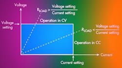
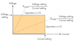
This offers an explanation to the common question: “Where is the CV button or the CC button on my power supply?” The answer is “there are no such buttons,” because the power supply’s mode is determined by the resistance of the load. At high resistance or open circuit, little to no current will flow and the supply will be in CV. Similarly, at low resistance or short circuit, a lot of current will flow and the supply will be in CC (Fig. 1).
Introducing Priority Modes
That brings us to the next concept: priority modes. Beyond CV and CC, a power supply can have both voltage- and current-priority modes. Priority modes govern the behavior of the supply. In voltage-priority mode, the power supply’s voltage-control loop is given priority. Most power supplies on the market today are simply voltage-priority power supplies with no means to give priority to the current loop. In fact, this is so common, that most engineers are never even aware that priority modes exist and simply expect voltage-priority-mode behavior from all of their CV/CC supplies.
Note that priority mode has nothing to do with CV and CC. A power supply in voltage-priority mode can be in CC or CV. Likewise, a power supply in current-priority mode can be in CV or CC. The priority mode simply defines the behavior of the supply as it transitions from CV to CC or CC to CV.
So what do priority modes mean? Below is an explanation of the power-supply behavior for each priority mode.
Voltage-Priority Mode
During startup in voltage-priority mode, the voltage is initially set to 0 V and the current is set to the current-setting value. Because it’s in voltage-priority mode, the CV loop is given priority such that the power supply starts in CV and voltage is the regulated parameter. The voltage begins at 0 V and starts to ramp up to the programmed voltage value under CV loop regulation in order to achieve clean, well-behaved performance with fast voltage rise time and minimal overshoot.
If the load is high impedance, such that RLOAD > (voltage setting/current setting), the power supply will stay in CV, cleanly regulating voltage, and the current will flow into the load. There will be little to no voltage overshoot as the voltage reaches the programmed voltage setting, as the power supply is cleanly regulating voltage.
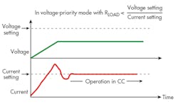
If the load is low impedance, whereby RLOAD < (voltage setting/current setting), the power supply will start in CV but the low load impedance will mean the voltage can’t climb to the programmed value. Instead, the sourced current will quickly hit the current setting and transition to CC, and the voltage will collapse. During the brief transition from CV to CC, as the CC loop takes over, it takes a moment to achieve regulation to the programmed current setting. This results in some momentary current-control instability, which could cause an overshoot in current (Fig. 2).
Basically, in voltage-priority mode, voltage will be well-behaved with minimal overshoots. However, current could overshoot during any CV to CC mode crossover transition, as current regulation isn’t given priority.
Current-Priority Mode
Now, let’s look at current-priority mode. During startup, in current-priority mode, the current is initially set to 0 A and the voltage is set to the voltage-setting value. Because it’s in current-priority mode, the CC loop is given priority so that the power supply starts in CC and current is the regulated parameter. The current begins at 0 A and starts to ramp up to the programmed current value under CC loop regulation in order to achieve clean, well-behaved performance with fast current rise time and minimal overshoot.
If the load is low impedance, whereby RLOAD < (voltage setting/current setting), the power supply will stay in CC, cleanly regulating current. There will be little to no current overshoot as the current reaches the programmed voltage setting, since the power supply is cleanly regulating current.
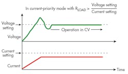
If the load is high impedance, whereby RLOAD > (voltage setting/current setting), the power supply will start in CC, but the high load impedance will mean the power supply can’t drive enough current into the load. Any current through the high load impedance will create a large voltage across the load, and the supply will quickly hit the voltage setting and transition to CV.
During the brief transition from CC to CV, as the CV loop takes over, it takes a moment to achieve regulation to the programmed voltage setting. This will result in some momentary voltage-control instability, potentially causing an overshoot in voltage (Fig. 3).
Basically, in current-priority mode, current will be well-behaved with minimal overshoots. However, voltage could overshoot during any CC to CV mode crossover, since voltage regulation isn’t given priority.
Summary
While priority modes have historically been implemented via analog design, modern power supplies are highly digitally controlled using digital signal processing (DSP), digital feedback loops, FPGAs, etc. The behavior of the supply, including priority modes, can be implemented digitally and, therefore, the fundamental block diagram of the power supply is no different when in voltage or current priority. In other words, the power supply doesn’t switch in different circuits or flow signals through different paths when in one mode or the other. The digital control system commands the supply to act differently to achieve voltage or current priority.
So, if you’re concerned about overshoots, select the appropriate priority mode. Use voltage-priority mode when voltage overshoots must be minimized, such as when biasing to the cores of low-voltage processors or FPGAs. Use current-priority mode when current overshoots must be minimized, or if your device under test is low impedance, such as when charging batteries or driving systems with large capacitors.
Looking for parts? Go to SourceESB.
This file type includes high-resolution graphics and schematics when applicable.


