This file type includes high-resolution graphics and schematics when applicable.
Bob Zollo, Solution Architect for Battery Testing, Electronic Industrial Solutions Group, Keysight Technologies
I’ve been working with dc power supplies and batteries for over 30 years now and every day I employ Ohm’s Law, V = I*R, to solve some problem or make some calculation related to dc power. If current is flowing, then there’s a voltage drop in the wires, in the connectors, in the relays, in the resistors, or in other circuit components. The more current, the bigger the voltage drop. The more resistance, the longer the wires, the thinner the wires, the more in-line connection…and again…the bigger the voltage drop. That voltage drop, described by Ohm’s Law, is generally the first thing I look at when someone is having trouble with a dc circuit.
A voltage drop occurs as long as the R in Ohm’s Law is positive. And R must always be positive—how can you have a negative resistance? In nature, R always seems to be positive. Yet Ohm’s Law works with negative R as well. With negative R, when current flows, it increases the voltage. It’s unnatural, but it works.
An Everyday Example of Negative Resistance
The most common application for negative resistance is remote sensing. It’s found on higher-current power supplies, where users are more likely run into voltage drops in load leads at higher currents. Using remote sensing, the power supply itself can adjust its output to compensate for the voltage drop in the load leads, even with changes in the current.
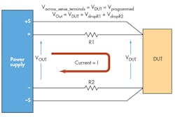
For remote sensing to work, the power supply must have four output terminals. The “+” and “–” terminals are the standard power-supply output terminals to which the load leads are attached, and through which currents will flow into the device under test (DUT). These are also called force terminals. The other two terminals are the sense terminals, typically labeled “+S” and “–S”. The wires connected to them are called the sense leads (Fig. 1).
1. Using remote sensing, voltage drops in load leads are compensated out so that the voltage at the DUT is the programmed voltage of the power supply.
The sense terminals, which are measurement terminals, have high input impedance so that no current will flow into the sense terminals. Since no current flows into the sense terminals, current will not flow through the sense leads. If no current is flowing, regardless of the resistance or gauge of the sense wires, there will be no voltage drop in the sense leads (thin wire, such as 18 or 22 gauge, can be used).
Therefore, voltage at the DUT will appear at the sense terminals, allowing the power supply to sense the actual voltage at the DUT. The power supply will regulate the voltage at the output terminals to keep the voltage at the sense terminals exactly at the programmed value, even as the voltage drop through the load leads changes during current changes.
So, conceptually, remote sensing causes the power-supply output to behave like it has a negative resistance in series with the load leads to overcome the resistance in the power supply’s output leads connecting the DUT. When the current goes up, the power supply’s output voltage also goes up (at its output terminals). At the same time, the current flowing through the real positive R of the wires has an equal and corresponding voltage drop. The result is a regulated voltage at the DUT’s sense point, regardless of the amount of current flowing.
Generating Negative Resistance
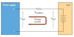
I recently came across another application for negative resistance. In this case, the DUT was a battery. This particular battery test required that the battery be charged with a constant voltage, at low current, through a fixed R. The easiest way to do this is to put a real R in the power lead between the power supply and the battery. However, as the user was interested to conduct this test at different R values, it was inconvenient to use a real fixed R because they would be forced to swap physical resistors for each pass of the test (Fig. 2).
2. In this battery test setup, the power supply slowly charges the battery through a fixed resistor RFixedReal.
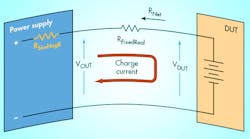
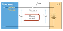
Instead, we placed a real R (in this case, 10 â¦) in the power lead. When the user wanted a different value, the test program would simulate an additional R in series with the real R. If the user wanted less than 10 ⦠total, the simulated R would be implement a negative resistance (Fig. 3).
To simulate the negative R, the control program, running on a PC, would continuously loop. At each iteration of the loop, the program would use the power supply to measure the charge current flowing into the battery. Then, the program would use Ohm’s Law to calculate the voltage rise across the simulated negative R and add that calculated voltage rise value to the programmed power-supply output constant voltage that was charging the battery.
3. Simulating the negative resistor RSimNegR results in RNet = RFixedReal + RSimNegR.
Therefore, as the battery charges, the current drops off and the voltage rise through the negative R gets smaller. Eventually, the constant voltage power supply will drive the battery to its the final charged voltage, at which point no charge current flows and, as a result, there’s no voltage drop or voltage rise.
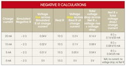
The table illustrates these calculations to achieve a net R of 8 ⦠by using a real R of 10 ⦠and a simulated negative R of –2 ⦠for the test setup in Fig. 3.
Note that this technique of using control software in a measure-calculate-reprogram loop to simulate R only works because this is a low-frequency near-dc application. The battery charges very slowly, so its current changes slowly. Each iteration of the simulated resistance loop took about 70 ms for the control program to make a current measurement (60 ms), calculate the new value (far less than 1 ms), and reprogram the voltage (10 ms). This 70 ms is very fast relative to the slow changes in current as the battery charges.
To the battery, this simulated R is indistinguishable from a real negative R (should such a thing exist), and, therefore, the net R (sum of simulated negative R and real R) behaves exactly like a real R of the same value. Hence, we have created a fully programmable R, albeit at near-dc speeds.
Note that this simulated R technique would also work for simulating positive resistance, but that’s the subject of another article.
