Deciding Between DC-DC Modules or Discretes When Facing a Space Jam
Download this article in .PDF format
Two trends in electronics show no signs of abating: The shift to portable and mobile products across multiple applications; and packing more and more features into each successive generation of equipment.
For the end user, it all sounds great. For the power-system designer, though, it translates into making the most efficient use of the available power, since portable devices are typically space-constrained with no room to add extra batteries.
The drive to get the most out of ever-smaller designs has led to the dominance of power systems based on switching, rather than linear, technology. Switched-mode power supplies (SMPSs) can attain efficiencies greater than 90%. That extends battery life in portable systems and frees up space otherwise needed for heat-dissipation components. Even in line-powered equipment, switching technology rules, because greater efficiency translates into lower operating costs. Consequently, switching designs are increasingly dominating all but the lowest-cost applications.
This increased efficiency has a downside, though, in the form of more complex design. Although not taught at Hogwarts, many engineers consider SMPS design in the same category as other Dark Arts such as Poisonous Potions and Unforgivable Curses.
Switching power supplies generate noise that interferes with sensitive analog and RF circuits. Their design also requires a diverse skill set, including knowledge of analog and digital circuits, magnetics, and control systems. The complexity can be overwhelming, especially for small development teams lacking an SMPS design specialist.
Rise of the DC-DC Power Module
Here's an ugly truth: Much as we power engineers might like to think otherwise, many system designers regard power more as a “necessary evil” than a point of product differentiation. Given the complexity of SMPS design and shrinking development cycles—another trend—it’s not surprising that engineers are looking for ready-made solutions that provide efficient power without the attendant headaches.
With dc-dc modules, multiple SMPS components are integrated into a single package to simplify the design process. Thanks to improvements in semiconductor and packaging technology, such modules have become increasingly popular. Their higher levels of integration simplify the overall design and consume smaller printed-circuit-board (PCB) area than a custom design.
Using a module reduces the time needed for design and verification. A market report by research firm Darnell Group found that a module-based design requires 45% fewer man-hours to complete than a discrete dc-dc regulator design. The reasons include robust designs, careful component selection, and EMI testing to ensure compliance with industry standards such as the EN55022 Class B Emissions test.
In fast-moving markets like consumer electronics, such a savings in development time can easily make the difference between being early to market with a new product and missing the market window altogether. In other applications, the development team can spend that time adding or refining new features.
DC-DC Module Overview
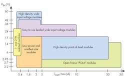
TI offers dc-dc power modules for input voltages up to 60 V and power levels up to 50 W. Modules are primarily step-down (buck) converters, although boost, buck/boost, and negative output modules are available.
1. A wide range of applications can take advantage of dc-dc power modules, with a variety of technologies servicing different power levels. (Courtesy of Texas Instruments)
In general, these dc-dc modules don’t provide galvanic isolation between input and output. However, for low-power isolated dc-dc conversion, there are standard brick modules up to 30 W, and the DCP and DCR families of miniature unregulated and regulated dc-dc converters come in 1- and 2-W versions.
Adding a dc-dc power module isn't an “all-or-nothing” approach. Depending on the application and power level, a range of integration options is available. In fact, many of the options overlap (Fig. 1). Several package types are used for dc-dc modules in this power range.
MicroSiL and MicroSiP Power Modules
For low-power applications where smallest size is a priority, the MicroSiL and MicroSiP power modules integrate the required passives and the integrated circuit (IC) into a single device. In both technologies, the IC is embedded into an FR4 laminate substrate and the inductor is mounted on top of the substrate material.
A MicroSiL device integrates the power inductor and the regulator IC; the required capacitors are external. The module outline and pinout are similar to a QFN-type package. For example, the TPS82085 power module can deliver 3 A from an 8-pin package that measures 3 mm × 2.8 mm. External input and output capacitors, feedback resistors, and an optional power-good resistor complete the design. MicroSiL devices are available with inputs up to 17 V.
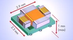
The fully integrated MicroSiP power modules integrate both IC and passive components into a single device with a ball-grid-array (BGA) format. The regulator is embedded inside the PCB, and the passive components are mounted on top. This is the simplest solution with the highest integration level. The smallest modules can achieve a footprint of less than 7mm2(Fig. 2).
2. The MicroSiP package integrates the switching regulator, inductor, input/output capacitors, and other passives; the solution is less than 1 mm high. (Courtesy of Texas Instruments)
The TPS8268x power module, for example, is a 1.6-A synchronous step-down dc-dc power supply in a single package. The five devices in this family offer output voltages from 0.9 V (TPS8268090) to 1.8 V (TPS8268180)
Another option for space-constrained applications is a Simple Switcher buck regulator integrated into a Micro-SiL module. The LMZ21700 Nano Module, for example, can drive up to 650 mA load at up to 95% efficiency with an input voltage range of 3 to 17 V and output voltage range from 0.9 to 6 V. Input and output capacitors and two feedback resistors complete the basic design.
Wide-Input-Voltage Modules
POL applications with wide input voltages up to 60 V can take advantage of Simple Switcher-based modules, which come in a variety of leaded and leadless packages. The 3-A LMZ23603, for example, can accept an input voltage between 6 and 36 V and deliver an adjustable output voltage as low as 0.8 V. The package for the LMZ23603 measures 10.16 mm × 9.85 mm; a complete solution requires three external capacitors and two external resistors.
High-Current DC-DC Open-Frame Modules
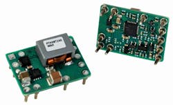
For higher-current applications where small size is important, designers can stay with a ready-made design by using a traditional open-frame module, such as one of TI's PTH family. The PTH08T240 (Fig. 3) is a non-isolated buck regulator that operates at up to 93% efficiency. It can supply up to 10 A; other PTH family members are able to supply up to 30 A.
The PTH pinouts conform to the specifications of the Point Of Load Alliance (POLA) consortium. POLA members, including Texas Instruments, offer pin-compatible, non-isolated, point-of-load plug-in power modules.
3. For higher currents, an open-frame module might be the best option for space-constrained applications. The PTH08T240 can deliver up to 10-A output current; its output is adjustable from 0.69 to 5.5 V. (Courtesy of Texas Instruments)
DC-DC Module Design Tradeoffs
There's no doubt that designers have a lot of choices when it comes to power modules—TI’s SiP family includes over 200 devices. But is a dc-dc module always the best solution for every design?
Integration doesn’t come for free—there are always tradeoffs to be considered. For example, a power module integrates various discrete components, so it must include a method of interconnecting them. A PCB is the preferred choice in the TPS82xxx MicroSiP family; the packages stack the inductor on top of the controller. Clearly, both of these design choices increase the height of a MicroSiP module compared to a discrete design.
Designing for minimum footprint requires reducing the inductor’s size. The inductance of a coil is proportional to coil area, all other factors being equal. Reducing the coil area while keeping the same inductance increases the amount of wire used. This in turn increases the dc resistance, which lowers efficiency slightly, especially at higher loads.
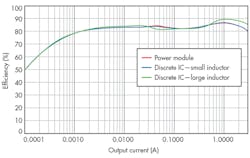
Figure 4 compares the efficiencies of three different solutions based on the TPS62085 3-A synchronous step-down converter: the TPS82085 MicroSiP version; a discrete design using a small-size inductor; and a discrete design using an inductor of the same value, but in a larger size.
4. The size of the inductor is the main cause of the performance difference between different versions of the same design. Power modules with stacked packages use smaller inductor sizes to reduce their footprint versus the equivalent discrete solution at the cost of increased height. (Image source: Electronic Design/TI)
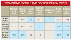
Comparing the relative sizes of these three solutions shows that the MicroSiP saves 22% in board area, but increases height by 33% compared to the equivalent discrete design. Compared to the discrete design with the larger inductor, though, the board-area savings are 43%.
Efficiency is another story. The results show that with identically sized inductors, the MicroSiP and the discrete design have identical efficiencies across their range. However, the discrete design with the large inductor has an advantage at higher currents, as much as 5% at full load.
Cost is a paramount issue for many designs. The cost of an integrated dc-dc module will be higher than that of the discrete regulator because it includes the inductor and perhaps other components. To get an accurate comparison, though, other costs must be included, such as increased assembly costs, the costs associated with a larger BOM, and non-recurring items like component selection and qualification, increased design time, potential layout issues, and PCB respins.
Comparing the costs of module and discrete designs involves more than just the components; it must also include manufacturing and design NRE costs. (Image Source: Electronic Design/TI)
The table summarizes the tradeoffs in cost and performance between a discrete power supply IC and a dc-dc module, without considering non-recurring costs. For this comparison, the inductor cost is estimated at $0.30, the capacitors at $0.05 each, and the resistors at $0.005 each.
Conclusion
For harried designers working within short design cycles, dc-dc modules offer several advantages in space-constrained designs, including a shorter design cycle and a smaller footprint. These advantages need to be weighed against potential performance differences and higher costs before deciding on the optimum approach for any given application.
