Download this article in PDF format.
During my engineering career, I’ve had the fortune of working in a comfortable, room-temperature environment. I’ve visited tropical factories where test equipment was being used in 90°F temperatures with 99% humidity, and I could imagine that same equipment being used on a mountaintop laboratory or in a military vehicle where it could get quite cold. While human operators may find these extreme temperatures uncomfortable, we must also consider the effects of these temperatures on the test equipment—and on the device under test.
Temperature Effects on Lithium-Ion Cells
Let’s start with an example of a device under test. In January 2016 (that means winter here in New Jersey), I was involved in some delicate testing work with lithium-ion cells. Our test goal was to very accurately measure the open circuit voltage (OCV) of the cells over a few days. So, we started making measurements in our comfortable laboratory environment.
We were actually quite surprised to find the voltage of the cells drifting up as time progressed. Now, we expected the cell voltage might drop over a few days as the cells slowly self-discharged (the subject for a future article), but we hadn’t considered that they might rise in voltage.
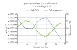
Figure 1 shows our test data. As you can see, the OCV of the cell varied inversely with room temperature. Because it was winter, the building temperature would experience a 2°C swing as the building cooled down during the cold overnight and warmed up during the day when the heating system turned on. The data shows that the cell had a temperature coefficient of voltage of approximately ‒110 μV/°C.
1. This plot reveals the temperature sensitivity of a lithium-ion cell.
Temperature Effects on DMMs and Other Instruments
To run these OCV measurements, we employed a very-high-accuracy Keysight 3458A 8.5-digit digital multimeter (DMM). Like the cell we were measuring, this instrument also has a temperature sensitivity, which means its accuracy varies with temperature. To achieve its high-end specifications, the 3458A combats temperature fluctuations in its environment through use of an auto-calibration (ACAL) function. The 3458A’s ACAL capability corrects for measurement errors resulting from the temperature drift of critical components following ambient temperature changes of less than ±1°C since the last ACAL.
Alternatively, some instruments counteract the effects of environmental temperature swings by keeping their own internal temperature constant with a reference circuit inside an “oven” that’s inside the instrument. The principle is simple: If you can keep the critical internal components at a constant temperature via an internal temperature-regulated oven, there’s no need to add in a temperature coefficient because the critical components’ temperatures are changing. For example, this technique is used to stabilize the temperature of oscillators in various time-measuring and signal-sourcing instruments.
Temperature Effects on DC Sources
Temperature sensitivity also applies to dc sources. Let’s look carefully at the specifications of a high-performance power supply, such as the Keysight N7970A Advanced Power System, rated at 9 V, 200 A, 1800 W (Fig. 2).
These power supplies are calibrated at a specific temperature, which is normally 23°C. However, the specific information about calibration temperature is listed on the calibration certificate that’s available for the power supply. As stated in the power supply’s specifications table, if the calibration temperature is 23°C, then the specifications are valid from 23°C ±5°C. This valid temperature range is usually documented in a footnote or in a paragraph at the top of the specification table. In the case of the N7970A, the temperature range for valid specifications is found in a footnote stating “At 23°C ±5°C after a 30-minute warm-up.”
2. The Keysight Advanced Power System (APS) is a family of dc power supplies that comprises 24 models at 1000 W (top) and 2000 W (bottom). These power supplies are carefully characterized with temperature coefficient specifications that allow users to source with very high accuracy at any temperature.
To apply this temperature coefficient, or tempco, specification, you must treat this like an error term. If you’re operating the power supply at 33°C, you need to factor in this tempco as follows:
- You want to set the voltage to 5.0000 V.
- The temperature is 33°C or 10°C above the calibration temperature of 23°C.
- Voltage programming tempco is ± (0.0022% + 30 μV) per °C.
- To correct for the 10°C temperature difference from calibration temperature: ± ((0.0022%/°C * 10°C * 5.0000 V) + 30 μV) = ± (110 μV + 30 μV) = ± 140 μV of temperature induced error at 10°C away from 23°C.
Note that this temperature-induced error must be added to the normal programming error, which is ± (0.03% +1.5 mV) as shown in the table. Calculating this programming error: ± ((0.03% * 5.0000 V) + 1.5 mV) = ± (0.0015 V + 1.5 mV) = ± 0.0030 V.
Therefore, the total error, including accounting for temperature, will be ± (0.00014 V + 0.003 V) = ± 0.00314 V. That means your output voltage will be somewhere between 4.99686 V and 5.00314 V when attempting to set the voltage to 5.0000 V in an ambient temperature of 33°C.
Since the 140-μV part of this error is temperature-induced, as the temperature changes, this component of the error will change, and the output of the power supply will drift. This drift with temperature is the direct effect of the power supply’s tempco.
Conclusion
Temperature matters. That’s why calibration labs carefully maintain and record their temperature. The devices that you’re testing will vary with temperature. The instruments that you use to make measurements on those devices will vary with temperature. The sources used to apply power to those devices will vary with temperature. By understanding temperature coefficients and how and when to apply them, you can improve your measurements and get good measurements down into the microvolt range.


