Eradicate Capacitive Current Spikes in LLC-Based Power-Supply Designs
Delivering elevated levels of reliability and power efficiency is crucial to all manner of modern power-system designs. Therefore, highly effective mechanisms need to be put in place that can rapidly respond to operational problems should they occur. One issue that engineers need to be fully aware of is synchronous-rectifier (SR) current inversion. This article addresses how to tackle the problem.
The LLC (two inductors and one capacitor) resonant topology has seen greater use in power-system design over the last few years. This is mainly due to its inherent ability to lower switching losses and boost overall efficiency when compared to other forms of hard switching topologies, such as flyback and forward.
Both of those features are extremely important in a world where conserving power budget is a high priority. This is true for all types of electronic products and equipment, whether they’re targeted at the enterprise-communications, industrial, or consumer spaces, and whether the motivation is to reduce running costs or adhere to legislative guidelines (it’s now increasingly likely that it will be a mix of both of these). As an example, with the huge predicted growth in cloud servers and data centers (driven by phenomena like the Internet of Things and Big Data), even small gains in power-conversion efficiency can save hundreds of thousands (possibly even millions) of dollars.
Issues with Timing and Parasitics
However, timing can negatively impact total system efficiency, with SR current inversion having a detrimental effect, as well as put sensitive components in danger. When an LLC power system is in heavy-load conditions, the body diodes integrated into each of the synchronous-rectification MOSFETs can begin to conduct right after primary-side switching has been completed.
In contrast, when the system is experiencing light-load conditions, the resonance capacitor voltage amplitude isn’t particularly large, so the voltage across the magnetizing inductance of the transformer is (conversely) quite small. The secondary-side synchronous rectification body-diode conduction therefore lags behind until the magnetizing inductor voltage builds up enough.
Capacitive current spikes, which are caused by parasitics, can stem from the output capacitors of MOSFETs. Their presence could prematurely activate the MOSFET (despite the delay in body-diode conduction) when under light-load conditions. Consequently, a reverse current will pass from output capacitor back to the synchronous rectifier, lowering the stored energy on the capacitor and impinging on efficiency levels in the process.
Preventative measures must be taken to safeguard against such situations, so that parasitics don’t initiate synchronous rectification and, subsequently, cause an unwanted reverse current flow. This means thorough examination of the system’s timing.
Rectifying the Situation
It’s estimated that the efficiency improvement derived from using a synchronous-rectification system that has functionality to protect against reverse current would, in most cases, be between 0.5% and 1.0%. At first that may seem a fairly minor gain; however, in LLC system stages that are already running at above 96% efficiency, such an increase is highly advantageous.
For example, if we take a power-hungry cloud server deployment that consumes several kilowatts of power, the reduction in day-to-day running costs will be considerable. Furthermore, the capital and operational expense associated with the accompanying thermal management will be significantly curbed, too, as the ramped up efficiency figures will result in a corresponding reduction in heat dissipation. It will also help save valuable printed-circuit-board (PCB) real estate, which is at a premium in these sorts of applications with densely packed components.
Specification of advanced devices that, in addition to being optimized for modern LLC resonant converter topologies, have functionality needed to protect against reverse currents, will assist engineers in further increasing power-system efficiency benchmarks. It will avert power losses caused by reverse currents, as well as improve long-term system reliability.
Driver Controller for Current Spikes
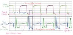
The plot illustrates the SR mis-trigger prevention function of the FAN6248 under light-load condition.
By utilizing a proprietary capacitive current-spike detection algorithm that it has developed, ON Semiconductor’s FAN6248 driver controller IC is able to tackle the current-spike issue plaguing synchronous-rectification circuits. The FAN6248 can increase the turn-on delay from 80 ns when the system is at full load operation to 380 ns when at light load. This means that the SR mis-trigger signal, which has the period of parasitic oscillation of drain sensing voltage just after a capacitive current spike occurs, is ignored if the period is less than 380 ns.
In addition, the FAN6248 has a pair of separate 100-V-rated sense inputs. Through these, the drain and source voltages across the two synchronous-rectification MOSFETs can be determined with a high degree of precision.
The figure provides details of how to prevent SR mis-trigger when there’s a capacitive current spike. By increasing turn-on delay to match with the system’s requirement, the turn-on trigger caused by a capacitive current spike is ignored, ensuring that reverse-current conditions will not be witnessed.
Overall, this technology can help eliminate SR mis-triggering in power-system designs. The upshot is that current inversion events will not have any bearing on a system’s operating efficiency, and the constituent hardware isn’t put at risk.


