Triboelectric Energy Harvesting Finally Gets Detailed Analytical Model
>> Website Resources
.. >> Library: TechXchange
.. .. >> TechXchange: Power Management
.. .. .. >> Topic: Energy Harvesting
Triboelectricity, which is defined as small-scale static-electricity charges generated by contact and motion between surfaces, seems like a winning “something for almost nothing” scenario. It can be used to generate energy that’s harvested and stored, and then used to power extremely low-power sensors and electronics. Now there’s a rigorous analysis and model-based framework, developed by a team of researchers at three UK-based institutions, which explains how much energy to expect from different contact geometries.
This team has come up with a generic, general-purpose model that can be modified to accommodate a wide range of triboelectric geometries and surface topographies. In their paper “Triboelectric nanogenerators: providing a fundamental framework,” published in Energy & Environmental Science (a journal of The Royal Society of Chemistry), along with its Electronic Supplementary Information, they present what they claim is a comprehensive explanation of the working principles of contact-mode triboelectric nanogenerators (TENGs) based on Maxwell’s equations.
Their model can be modified to calculate the current, voltage, charge, and power output under different experimental conditions. This is in contrast to the few models that exist and are restricted to known simple geometries, derived using the parallel-plate capacitor model.
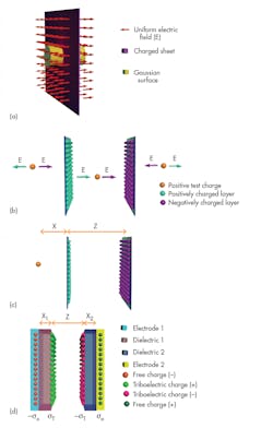
1. The figure illustrates the following: the electric field distribution perpendicular to an infinitely large charged sheet (a). The overall electric field resulting from two oppositely charged, infinitely large layers (b), and deriving the expression for the overall electric field originating from two oppositely charged surfaces (c). The structure and the charge distribution of a typical contact-mode TENG (d). (Source: The Royal Society of Chemistry)
The team’s approach introduces the concept of a distance-dependent electric field derived using the finite dimensions of the charged layers (a factor not taken into account in previous models) and is applicable to almost any surface or geometry (Fig. 1). The analysis reveals numerous new features and characteristics of TENGs, and the authors maintain that it provides the first platform to simulate non-planar complex TENG geometries. As a result, the model works as a guide in designing TENGs for different applications, and for optimizing parameters to achieve high efficiency.
Model First, Then Verify Experimentally
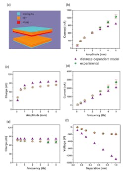
Of course, models that claim to be accurate and useful are one thing; experimental confirmation and verification is another challenge. To test the validity and usefulness of their model, the team built a TENG using carefully prepared and assessed poly(dimethyl siloxane) (PDMS) and poly(ethylene terephthalate) (PET) as the triboelectric contact surfaces. The layers were contacted and separated (pre-charged) 3000 times using a sinusoidal motion (a standard test condition) before taking the electrical measurements, to ensure that the TENG surfaces were saturated with static charges.
2. The TENG device architecture: A comparison of short-circuit current ISC and open-circuit voltage VOC; experimental observations against the predictions from the distance-dependent model (a). Peak ISC (b) and output charge (c) under increasing amplitude H, at f = 1 Hz, and peak ISC (d) and output charge (e) under increasing f, at H = 1 mm. VOC at increasing separations of TENG layers (f). (The closed purple triangles represent the distance-dependent model while the closed green circles represent experimental points measured. (Source: The Royal Society of Chemistry)
They then took current and voltage measurements using Keithley’s 6487 picoammeter and 6517B electrometer, respectively. The measured current signal was integrated over time to evaluate the accumulated free charge over a positive or negative current half-cycle (Fig. 2).
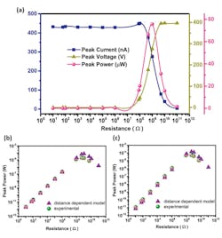
Finally, the current was measured using load resistors connected across the TENG, and power dissipation was calculated using the standard formula P = I2R (Fig. 3).
3. The 3-working-region behavior of the TENG power output predicted by the distance-dependent model, against different load resistors (f = 1 Hz, H = 1 mm), shows the comparison of the experimental and predicted peak-power outputs under different resistances (a); f = 1 Hz (b) and f = 2 Hz (c), where H = 1 mm. (Source: The Royal Society of Chemistry)
The published paper contains many other graphs that compare theory and experimentation from different perspectives. There was close agreement with respect to charge, current, voltage, and power. Other results show theory versus experiment with respect to surface area and separation distance.
Unlike the conventional explanations, the distance-dependent model explains the electric-field propagation and superposition, polarization of the dielectric TENG layers and its effect on the electrodes, potential build-up that generates the voltage in the device, and the free-charge induction on the device electrodes that affects the current and charge, many under different motion profiles.
>> Website Resources
.. >> Library: TechXchange
.. .. >> TechXchange: Power Management
.. .. .. >> Topic: Energy Harvesting


