How to Extend Battery Run-Time for Wearable Applications
Download this article in PDF format.
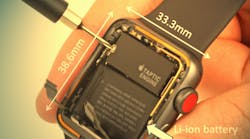
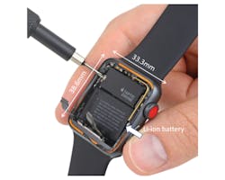
“Doing more with less” isn’t just a line from your CEO’s latest speech about corporate cost-cutting—it’s practically a mantra for designers of wearable electronic devices. Every new generation of smartphone, fitness band, and smartwatch offers an ever-increasing array of features. The Apple Watch Series 3 (Fig. 1), for example, includes an accelerometer, gyroscope, heart-rate sensor, microphone, speaker, barometric altimeter, ambient light sensor, Wi-Fi, Bluetooth, NFC, GPS, and optional LTE phone. Oh, and it tells the time, too.
1. Like most wearables, the Apple Watch Series 3 leaves little room for its 279-mAh battery. Nonetheless, the watch can run for up to 18 hours with occasional use. Just be careful about talking on the phone—that can reduce the run-time to as little as one hour. (Source: ifixit.com)
This increased functionality results in greater power usage. Add in the continuing trend toward smaller, thinner packages, and something’s gotta give.
In this case, it’s often the space allotted for the battery. No longer do current-generation smartphones allow the user to swap out the battery when its performance starts to degrade; the user-replaceable battery has become a victim of the drive toward ever-thinner devices.
There’s even less space available for a battery in a wearable. A smartwatch or fitness band often only has room for a single-cell Li-Ion battery with a voltage of 3.8 V and a capacity of 130 to 410 mAh.
Not surprisingly, a smaller battery has a smaller capacity—less energy for those power-hungry new features. As a result, one of the most common complaints from buyers of wearables is short battery life.
Start with a System-Level Approach for Lowest Power Consumption
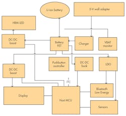
The combination of increased power consumption and a smaller battery forces the designer to look for power savings at every opportunity. An effective system-level approach is to divide up the functional blocks, group them into power domains based on their common needs, and then formulate the best approach for each domain to maximize efficient use of power (Fig. 2).
2. A typical wearable architecture can be segmented into several blocks based on their shared power profiles. The most efficient design optimizes the power strategy for each block. (Source: TI Training video: “Nuances in ultra-low power designs for wearable products”)
For instance, some domains can be completely turned off when not in use. Examples include radios and highly duty-cycled functions that aren’t time-dependent.
Other domains need low power in standby mode, but also need to be able to respond quickly. Examples include microcontrollers and sensors that spend most of the time asleep, but wake up to perform scheduled functions or respond to user inputs.
Another domain might put the emphasis on high efficiency under full load. The ability to fully disconnect the battery from the rest of the system is always an advantage, to ensure that the battery retains charge while the product is being shipped or stored in the warehouse.
For more information on segmenting domains and optimizing the power architecture, view this video from Texas Instruments.
Battery-Management System Blocks for Wearables
Turning to the battery-management system (BMS) itself, Li-ion is the most popular chemistry for small rechargeable batteries. It has many advantages when compared to its competitors, but Li-ion batteries suffer from a relatively small safe operation area (SOA). Conditions such as overcharging, over-discharging, or overtemperature can have potentially catastrophic results. Thus, the BMS must carefully monitor the current, voltage, and temperature during charging and operation.
Three primary goals of a BMS design are to minimize the BMS current consumption during operation to maximize the available battery energy; minimize the time needed for recharging; and recharge the battery to the greatest degree possible.
The battery run-time is affected by various factors, including battery capacity, power consumption, and usage patterns, among others. For small batteries, two BMS parameters have the greatest effect on battery capacity and runtime: the leakage current and charging termination current.
Leakage Current
To demonstrate the effect of the BMS leakage current, consider a wristband with a 50-mAh battery that can support 30 days of operation.
If we assume that the BMS is ideal and consumes zero current, the baseline current consumption of the rest of the wearable design is therefore 64 µA. By adding different BMS leakage currents, the battery run-time will be reduced by different amounts. With 75 nA of leakage, there’s a negligible difference; the battery can still support 30 days of operation. A leakage of 5 µA, however, reduces the battery run-time by two days, and a leakage of 20 µA reduces run-time by seven days, or 23%, so a low leakage current is a requirement for a wearable battery-management system.
Termination Current
Why is the termination current important? It’s the charging current at which the charger ceases operation because it considers the battery fully charged. If the charger sets the level too high, it will stop charging the battery while usable capacity remains, needlessly shortening system run time.
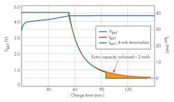
3. Shown are the charge cycles for a 41-mAh battery with 4- and 1-mA termination currents. (Source: TIE2E Community: “Advanced charging features extend battery run time for wearables”)
Figure 3 illustrates that the charging current declines over time. The graph also shows the variation in capacity for a 41-mAh battery after two different charging cycles, both of which begin with a charging current of 40 mA. The green line represents a charging cycle with a normal 10% termination ratio; i.e., a termination current of 4 mA. The red line represents a charging cycle with a 1-mA termination current; this provides an extra 2 mAh of capacity—a 5% improvement.
There’s a tradeoff in capacity versus time: The 2 mAh took an additional 50 minutes for this battery (146 minutes charge time versus 97 minutes.) Is it worth it? That’s a decision for the designer, of course, but an extra 5% can mean two more hours of operation for a smartwatch.
The smaller the battery, the more critical the termination control. A charger with a termination current of 5 mA will waste more than 10% of the capacity of a 20-mAh battery.
Let’s discuss the two most important blocks in a portable or wearable BMS: the battery charger and the battery fuel gauge.
Battery Charger
A battery charger must monitor the state of the Li-ion battery at all times during the charging process to keep it within the safe operating area.
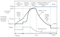
As we mentioned earlier, Li-ion is very sensitive to excursions outside its safe operation area, and a battery charger must follow a precise charging sequence. A deeply discharged battery, for example, can’t accept the full charging current without overheating, so the charging sequence begins with a pre-conditioning phase that applies a preprogrammed reduced current for a specified time. When the battery voltage rises to a safe level, the battery charger rapidly increases the voltage to a preset value while monitoring the IC temperature to ensure that it remains below the operating limit. This is the thermal-regulation phase.
During the current-regulation or “fast-charge” phase, the battery is charged at a preset constant current that’s a function of the battery capacity. The battery voltage gradually rises until it reaches 4.1 V or 4.2 V; the precise value depends on the Li-ion electrochemistry being used.
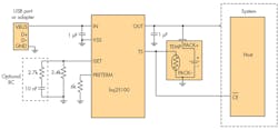
4. The bq25100 can deliver up to 250 mA with accuracies of 1% for charge voltage and 10% for charge current. The optional RC circuit improves current stability for currents below 50 mA. (Source: TI bq25100 PDF, p. 22)
In the next phase, the charger switches to the constant-voltage phase to prevent overcharging. With a constant voltage, the current gradually declines as the battery charge increases. When current reaches the termination value, it ends the charging. As we’ve seen, with a wearable battery, it’s important to precisely control the termination point to attain the maximum battery capacity.
Several TI battery chargers are suitable for portable and wearable use. For the smallest batteries—in hearing aids, for example—the bq2510x (Fig. 4) is a great choice. It’s a highly integrated family of single-cell Li-ion and Li-Pol chargers that features a compact chip-scale IC package size of 1.6 by 0.9 mm; the total solution is as small as 2.1 by 2.2 mm. The device has a termination current of less than 1 mA to maximize the available capacity of small batteries and an extremely low leakage current of 75 nA (max).
Figure 5 shows the charging profile for the bq2510x. The charger is very flexible, allowing the designer to program the fast-charge current and precharge/termination current. It can accept power from either a USB connection (100-mA limit) or dc adapter. The bq2510x includes system-level protection features such as input undervoltage lockout (UVLO), input overvoltage protection (OVP), and thermal regulation; it also monitors the battery-pack thermistor temperature via the TS pin.
5. The bq2510x family of battery chargers follows a precise charging profile to ensure safe charging and maximum battery life. (Source: TI bq25100 PDF, p. 13)
Applications with larger batteries require larger charging currents. In these cases, the bq24040 can supply a charge current from 10 mA to 1 A with a termination current of 6 mA. This device has a solution size of 2.5 by 3.5 mm, and a range of features that includes charge status indication, as well as programmable pre-charge and termination rates. It’s a popular linear charger for low-power applications.
The charging voltage of a Li-ion cell depends on its battery chemistry. A lithium nickel-manganese-cobalt (NMC) cathode, for example, has a 4.2-V charging voltage, so the available voltage options are of great interest to designers. The bq24040 family has 4.2 V and 4.35 V available; the bq2510x offers 4.06 V, 4.2 V, 4.3 V, and 4.35 V, depending on part number.
Battery Fuel Gauge
The battery fuel gauge is the other key component in a wearable BMS. This component predicts the battery capacity and other characteristics of a single Li-based rechargeable cell. Battery capacity is expressed as state of charge (SoC). It’s a measure of the available energy in the battery, from 0% (empty) to 100% (fully charged). The fuel gauge also provides a battery state-of-health (SoH) estimation. This parameter is an indication of the current condition of the battery and its remaining useful life.
Texas Instruments’ proprietary Impedance Track SoC algorithm is a key part of TI’s high-accuracy battery fuel gauges. The algorithm distinguishes between three battery states: charge, relaxation (no load), and discharge. During charge and discharge, it measures the current flow and recalculates the change in depth of discharge (DOD) each second. When it detects a relaxation state, the algorithm measures the open-circuit voltage (OCV), corrects for any residual current flow, and then updates the DOD baseline value by linear interpolation from a chemistry-dependent lookup table.
The algorithm gives high-accuracy SoC predictions for the lifetime of the battery across a wide variety of operating conditions.
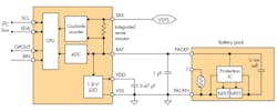
The bq27421-G1 (Fig. 6), which includes Impedance Track technology, is TI’s lowest-power fuel gauge for single-cell Li-ion batteries. Housed in a 9-ball, 0.5-mm-pitch chip-scale package, its 1.62- by 1.58-mm size is ideal for wearable applications. The device measures the charging and discharging of the battery by measuring the voltage across an internal 7-mΩ sense resistor, a technique called coulomb counting.
6. The bq27421-G1 battery fuel gauge provides SoC and SoH indications with minimal microcontroller involvement. (Source: TI bq27421-G1 PDF)
The bq27421-G1 uses an integrated temperature sensor to estimate battery-cell temperature. Alternatively, the system microcontroller can provide temperature data.
This device also has several low-power modes for improved power efficiency: initialization, normal mode, sleep, hibernate, and shutdown. In shutdown mode, the bq27421-G1 consumes only 600 nA, which is negligible compared to the Li-ion cell self-discharge rate.
The bq27421-G1 offers ease of configuration and flexibility of battery-pack selection. The system microcontroller can obtain cell DOD information via the industry-standard I2C serial bus.
Conclusion
With an ever-increasing list of features, severely limited space for the battery, and a continual demand for longer run-time, wearables present a difficult challenge to the power-system designer. Making the most of the available capacity requires a system-level approach to power efficiency coupled with individual components that tightly control battery operation while consuming minimal power.
The Texas Instruments portfolio of single-cell battery management products offers multiple options for designers who want to develop compact designs that maximize run-time in a wearable application.
