LLC Resonant Converters Raise the Power-Efficiency Bar
Download this article in PDF format.
Switch-mode power supplies (SMPS) are known for their superior efficiency. And while they achieve a significant level of efficiency, the quest to improve it even further continues to march on. One development helping to attain that goal is LLC resonant converters. These unique SMPS use resonant circuit techniques to reduce switching losses.
However, to receive any gains from resonant techniques requires a sophisticated controller. Now such controllers are available, and they feature additional power savings that further boost efficiency.
What the Devil is an LLC Resonant Converter?
Switching transistors are vulnerable to significant losses, which occur during the turn-on and turn-off intervals. When the transistor is off, no power is dissipated. When the transistor is on, its low on-resistance keeps power dissipation to a minimum. During switching times, though, the transistors pass through their linear region where their resistance is higher, which means dissipation of power. Luckily the transition periods are short. Reducing the switching time substantially cuts down the power consumption.
The switching time is determined by the transistor’s specifications, but also by other circuit characteristics. Also, keep in mind that sharp pulse edge transitions produce transients that generate noise and electromagnetic interference (EMI). Therefore, a key goal in design is to reduce the switching time by using a higher switching frequency. Though EMI still occurs at faster switching rates, there’s a beneficial reduction in power consumption. Using LLC resonant techniques can bring about that desired reduction in power consumption.
LLC, of course, refers to the use of two inductances (L) and a capacitor (C). This combination establishes resonance at the switching frequency. As a result, the switching transistors see a sine wave and are enabled to switch at the zero-crossing points or near zero. This has the effect of reducing switching losses in the transistors.
The benefits of going this route are that it allows for higher switching frequencies, which, in turn, reduce the size of transformers and filters (and related components) as well as minimize switching-transistor heat dissipation and the need for large heat sinks. All of these benefits are achieved while increasing the circuit’s overall efficiency.
Resonant Example
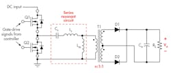
1. In this simplified version of an LLC resonant dc-dc converter, series resonance depends on the resonant capacitor Cr and the combination of the resonant inductor Lr and Lm. Lm is the magnetizing inductance of the transformer primary winding.
Figure 1 shows a dc-dc converter using resonant techniques. The half-bridge transistors Q1 and Q2 are alternately turned off and on by 50% duty-cycle square waves. This produces an input voltage, which is an ac square wave that excites the circuit. An inductor (Lr) and capacitor (Cr) are connected in series with the transformer primary winding. The magnetizing inductance of the primary winding Lm appears in series with Lr, increasing the overall series inductance. The L and C values are selected to resonate at the switching frequency. The resonant frequency is determined by the well-known formula:
fr = 1/2π √(LC)
Remember that at the resonant frequency, XL cancels XC, leaving only any series resistance to determine the Q of the circuit:
Q = XL/R
The effective series resistance is determined by the inductor and primary-winding resistances added to the equivalent reflected load resistance.
While the applied voltage is an ac square wave, the primary circuit is resonant and “rings” or oscillates at the resonant frequency and the current is sinusoidal.
The switching signals to the transistors are timed so that the switching times occur at the zero-voltage or -current crossing points. With zero current or minimal current, transistor current is zero or very low, so power dissipation during the on-off transitions is zero or minimal.
A Digital Controller to Implement LLC Resonant SMPS
Texas Instruments’ UCC256301 is an LLC controller that operates over the 35-kHz to 1-MHz range. It’s suitable for use in digital TVs, power tools, LED lighting, ac-dc adapters, and other modern power supplies where efficiency is the most important. Its features and benefits include integrated high-voltage startup, x-cap discharge, robust fault protection, and a unique control method.
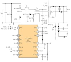
Figure 2 illustrates an LLC resonant dc-dc converter using the UCC256301. Note the resonant components Lr, Lm, and Cr. Also note the VCR and ISNS signals’ input to the controller IC, and the feedback (FB) from the output.
2. This practical LLC resonant converter uses the UCC256301 controller. Shown are the feedback signals for HHC to the controller at pins ISNS, VCR, and FB. (Source: TI blog “Up your game with LLC resonant converters”)
The UCC256301 uses a control technique called hybrid hysteretic control (HHC) to improve transient response. Transient response refers to how an LLC converter responds to rapid load changes. To avoid using large load capacitors to minimize output-voltage changes, the UCC256301 uses a combination of frequency-control and charge-control feedback techniques.
HHC also results in an industry-low standby power consumption of 40 mW with no load, which sets the UCC256301 apart from other controllers. Many if not most electronic devices consume power even when they’re in sleep or standby mode.
In an effort to reduce global power consumption, several countries have mandated regulations to make our world a greener place. Texas Instruments’ family of LLC resonant controllers helps meet the increasing power demands of the latest designs.
The UCC256301 is accompanied by a full set of support materials, such as evaluation modules, a design calculator, simulation models, datasheet, and relevant application notes. One of TI’s training videos also discusses how to deal with an underachieving LLC controller.


