Supply Meets Demand: Use Multiphase Converters to Solve Tough Power Design Challenges
Download this article in PDF format.
No matter what the latest microprocessor, FPGA, or ASIC has in store, their demands always seem to be the same—the need for higher current while operating at lower voltages. A core voltage of less than 1 V is common. Power supplies for current-generation microprocessors must be able to supply the core with a current up to 200 A. Dynamic load variations of up to 500 A/µs are also possible. During these transients, the voltage to the processors must stay within a narrow window, often ±3%.
For lower-current applications up to approximately 40 A, single-phase buck topologies work well, but as currents increase, their efficiency declines and power dissipation becomes an issue. Combining high efficiency and fast transient response presents another problem. The transient response depends on switching frequency, but raising the frequency lowers efficiency due to increased switching losses.
The multiphase regulator has higher efficiency and faster transient response than a single buck regulator of equivalent power. A multiphase design consists of several single buck-regulator stages connected in parallel driving a common load. Each regulator stage has its own inductor and power MOSFETs, but the input and output capacitors are shared.
High-power processor applications such as servers, PC desktops, and laptops have traditionally been the primary homes for multiphase buck regulators. However, they’re becoming an attractive option for space-constrained smartphones and tablets, too, as those applications steadily increase their peak power demands.
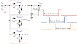
1. Shown is a multiphase buck regulator with its three phases. (Source: TI Application Report: “Multiphase Buck Design From Start to Finish (Part 1)” PDF, p. 2)
Figure 1 shows the principle of operation of a multiphase buck regulator with three parallel stages, known as phases. The input voltage is VIN; the output voltage is VOUT; the output inductors are L; and the input and output capacitors are CIN and COUT, respectively. The high- and low-side power FETs for each stage are also shown. Each phase is switched at the same frequency but at a different time, based on the number of power stages. The three-phase converter shown requires three switching signals, phase-shifted by 120 degrees (0°, 120°, 240°).
Multiphase Control Techniques
Multiphase regulators use the same control methods—voltage-mode or current-mode PWM control, for example—as their single-phase counterparts. The high- and low-side power FETs are driven in a complementary manner with a given duty-cycle, D, based on the input and output voltage relationship. A multiphase converter offers additional advantages, though, such as flexible phase configurations and phase shedding to optimize efficiency across the load-current range.
Multiphase designs also have standard protection features, such as overvoltage and undervoltage protection, short-circuit protection, in-rush current limiting, and output-voltage slew-rate control.
Multiphase Advantages and Disadvantages
A multiphase regulator has several important advantages over a single-phase design: reduced input and output capacitances, better thermal performance and efficiency with high loads, and better response to load transients. Let’s discuss these in turn.
Reduced input capacitance
Adding more phases reduces the RMS input current flowing through the decoupling capacitors, and so reduces the voltage ripple on the input voltage VIN. Versus a one-phase design, the total input current waveform of a multiphase buck has both a lower peak value and a lower RMS current value. This not only reduces CIN requirements, but also reduces stress on the high-side MOSFET of each phase. On top of that, it’s easier to pick a power transistor thanks to the wider choice of available components.
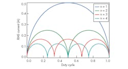
2. Increasing the number of phases reduces the normalized RMS current through the input capacitors. (Source: TI Application Report: “Multiphase Buck Design From Start to Finish (Part 1)” PDF, p. 5)
How much benefit accrues from adding more phases? Figure 2 compares the normalized RMS current flowing through the input capacitors versus the regulator duty cycle as the phase count increases. The addition of a single phase can reduce the RMS current by 50% or more, depending on the duty cycle. At several points, the RMS current even drops to zero as the individual ripple currents of each phase cancel each other out.
Note that the zero-current points are a mathematical ideal, not a practical option. System noise, load transients, and interphase variations will thwart this desirable state of affairs.
Reduced output capacitance
Each phase in a multiphase regulator has the same inductor ripple current as an equivalent single-phase design for the same operating conditions. However, because the phases connect to a common output node, their inductor currents sum together, so that the output capacitors are charged and discharged at the same time. This concurrent operation results in a lower overall ripple current.
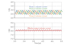
Figure 3 shows the ripple cancellation for a three-phase converter. The total current ISUM flowing through the output capacitors has a lower peak-to-peak value than an individual phase current. The lower ripple allows the design to satisfy the VOUT ripple specification with less output capacitance.
3. As can be observed, inductor ripple current was cancelled in a three-phase converter. (Source: TI “Merits of multiphase buck DC/DC converters in small form factor applications” PDF, p. 4)
The graph of normalized output capacitor ripple current versus the number of phases looks similar to the input capacitance graph in Fig. 2, with points of zero capacitance. Not surprisingly, eliminating the output capacitors is similarly impractical.
Better thermal and efficiency performance at high loads
The multiphase converter divides the power between several inductors and several power FETs, resulting in less power per stage. This allows each stage to operate more efficiently, which reduces component and board temperatures and gives the designer a greater choice of components.
The multiphase controller can vary the number of active phases to maximize efficiency at different load points. As the current demand by the load decreases, the controller can turn off phases (phase shedding) to reduce switching loss and gate-drive power consumption. At the lightest loads, the multiphase regulator can operate with a single phase, even switching to discontinuous-conduction mode if needed. Conversely, as the load increases and conduction losses in the FETs and inductors begin to dominate, the controller can turn on additional phases.
Most current multiphase controllers allow the design to tune the switchover points to optimize the efficiency for a particular application.
Improved transient response
During a transient event, the multiphase controller can use phase shedding to overlap phases during a load step, or turn off all of the phases during a load release.
When multiple phases are operating simultaneously, their inductors are effectively in parallel. This divides the equivalent inductance seen by the output by n, where n is the total number of phases.
With a smaller equivalent inductance, the multiphase regulator can supply charge to the output capacitors more quickly, reducing the undershoot. Each inductor stores less excess charge to transfer to the output caps when the phases are all turned off, reducing the overshoot.
Multiphase regulators have many advantages, but a few challenges stand in the way of a successful design. Phase management is perhaps the biggest challenge. For highest performance, the design must balance the current evenly between active phases to provide optimal ripple cancellation and equally distribute the thermal load. The controller must also be able to quickly add or remove phases to accommodate transient load variations.
These features come with additional complexity. Adding a shunt resistor in series with the inductor or using the inductor’s parasitic dc resistance are two standard methods of measuring phase current. Both techniques are sensitive to component placement and signal routing. The sense circuitry for each phase requires additional passive components to provide filtering; the shunt resistor also dissipates additional power.
Adding more phases to a converter also increases the bill-of-materials (BOM) cost and PCB area. The price of the added inductors and FETs must be weighed against the higher cost of sourcing more robust components and needing higher capacitor counts to implement a single-phase regulator instead. A balance between current capabilities and thermal performance versus overall phase number must be found.
Design Example
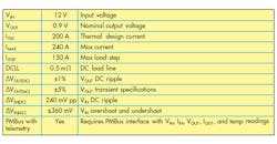
Let’s look at some of the design details for a multiphase design suitable for a high-performance processor or FPGA application. The design must provide 200 A at 0.9 V from a 12-V input, with a maximum load step of 150 A. Consult application report SLVA882 for a detailed discussion of the calculations and tradeoffs. Figure 4 shows the application requirements.
4. These are the application requirements for the 200-A multiphase regulator. (Source: TI Application Report: “Multiphase Buck Design From Start to Finish (Part 1)” PDF, p. 10)
The specification calls for a 200-A thermal design current (ITDC) and 240-A maximum current IMAX. The design requires six phases to keep the maximum current of each phase below 40 A.
A six-phase solution will only have 33 A per phase at ITDC and 40 A at IMAX, providing a more manageable power-loss scenario. The additional phases also significantly reduce the number of capacitors needed to maintain regulation during load transients. Most of the parameters will be familiar to power-supply designers, but a couple merit further discussion.
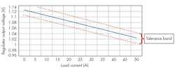
The current required by the processor core is very dynamic. When the core is idling, it needs relatively little current. As core utilization increases, so does the current consumption. Thus, many processor and DSP manufacturers use a DC load line (DCLL) to specify the regulator’s output voltage and tolerance over the required current range. The slope of the DCLL is linear, so the regulator appears as a pure resistive source to the load.
The allowable variation of the regulator output voltage at different load currents is specified as a tolerance band around the load line (Fig. 5). The DCLL in the design under discussion is 0.5 mΩ.
5. Here’s a 2-mΩ dc load line specification for a CPU core. (Source: Intel)
The Power Management Bus (PMBus) is an industry-standard two-wire interface that eases communication with a power converter. It’s based on SMBus, a version of the venerable I2C protocol, and is included in many current-generation single and multiphase regulators. Adding PMBus capability simplifies power-up/-down sequencing, output-voltage control, reporting of operating conditions, and fault recording.
Design Details: Selecting the Inductor
When choosing an inductor, start with the switching frequency. A frequency of around 300 kHz can provide low switching loss and high efficiency at the expense of slow transient response. A lower frequency requires a larger inductor, and the control-loop bandwidth must be set lower than at a higher frequency. Conversely, a higher switching frequency, say 1 MHz, allows for a faster transient response but incurs greater switching loss.
A switching frequency of 600 kHz provides a compromise between high efficiency and fast transient response. With a ripple current target of 25%, the standard buck converter calculations yield an inductor value of 138 nH. A 150-nH choke is the closest standard value.
With this same ripple and using single-phase operation as the worst-case scenario, the same equations give an output capacitance of 214 µF. Consult SLVA882 for more details.
Design Details: The Power Stage
As we’ve seen, determining the phase current is a major challenge in multiphase converter design. A smart power stage simplifies this aspect of the design by integrating the driver, the power MOSFET, and the current-sense circuit into a single package. When paired with a compatible controller, such a solution offers increased sense accuracy, reduced component count, and reduces PCB signal-routing issues.
This design uses the CSD95490Q5MC power stage: it’s a highly-optimized design for use in a high-power, high-density synchronous buck converter. The device integrates TI’s NexFET third-generation power MOSFET. This technology reduces parasitic capacitances by about 50% compared to the earlier TrenchFET, while offering comparable RDS(ON). Lower capacitance equates to lower input gate charge and shorter voltage transients during switching, allowing for an increase in the operating frequency.
The CSD95490Q5MC integrates the driver IC and power MOSFETs with the current- and temperature-sensing functions for a complete power stage. The device can operate at 75-A continuous current, switch at up to 1.25 MHz, and achieve an efficiency of greater than 90% at the ITDC value of 33 A, easily meeting the application requirements. The CSD95490Q5MC comes in a small SON5X6 DualCool package with thermally enhanced topside cooling.
Design Details: The Controller
The TPS53679 dual-channel multiphase controller is a good fit for this ASIC core rail, since it uses TI’s D-CAP+ modulator optimized for multiphase control and phase-current balancing. For more details on the different D-CAP modulators, see this training module. Six PWM channels in a small package accommodate a variety of power stages. PMBus communication satisfies the telemetry requirement and provides for dynamic phase-shedding thresholds to achieve optimal efficiency over the whole load range.
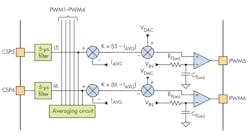
The TPS53679 uses TI’s patented AutoBalance circuit to balance the phases for equal current sharing. The circuit senses the average phase current and adjusts the pulse widths of the different phases to equalize their currents.
Figure 6 shows the circuit. A PWM comparator initiates a pulse when the feedback voltage meets the reference value. The VIN voltage charges CT(on) through RT(on). The pulse terminates when the voltage at CT(on) matches the on-time reference, which normally equals the DAC voltage (VDAC).
6. The AutoBalance circuit compares each phase current to the average value and adjusts the pulse width as needed. (Source: TI TPS53667 PDF)
The circuit operates as follows: If the filtered current from phase X, (Ix) is the same as the average value, the output from the first summation stage is zero, and VDAC sets the PWM pulse width. If Ix > IAVG, then the first stage generates a negative offset that’s subtracted from VDAC, reducing the pulse width and hence the phase current. Conversely, if IX < IAVG, then a longer pulse is generated that increases the phase X current.
Conclusion
As ASICs, DSPs, and microprocessors demand ever-increasing performance from their power supplies, traditional single-phase solutions are no longer up to the challenge. Multiphase buck converters offer several advantages, such as higher efficiency across the performance envelope; lower output ripple voltage; and better transient performance.
On that front, Texas Instruments has a broad portfolio of multiphase converters to meet the most demanding server requirements.

