Download this article in PDF format.
Nikola Tesla was right—you can transfer electrical power wirelessly. He demonstrated it in several ways in the late 19th century. Yet, as usual, he was ahead of his time. Up until recently, that work was generally lost, ignored, or dismissed. Now researchers and developers are finally finding ways to make wireless power transfer happen in a practical manner.
Wireless power transfer is used primarily to charge batteries in an incredible range of products. The earliest applications were plain inductive chargers in electric toothbrushes and shavers. Today, most wireless chargers are for smartphones, wearables, and even laptops. Other consumer targets include hearing aids and golf carts. One application that makes sense is wireless charging for hybrid electric vehicles (HEVs) and full electric vehicles (EVs). And a common industrial application is wireless charging of electric forklifts.
This article takes a look at the concepts behind the technology and provides an update on this movement today. Also, for a contrasting opinion on the wireless rage, see "Cordless Chargers: An Alternate View" at the end of the article.
The Theory of Wireless Power
There are two basic ways to transfer electrical energy without wires: near field and far field. The near-field method is basically just magnetic coupling. The operation is that of a transformer, where a transmitter (TX) coil is the primary winding and a receiver (RX) coil is the secondary winding.
The power transfer is wireless; no direct electrical connection exists between the transmitter and receiver. However, the key to making this work well is to keep the distance between TX and RX as short as possible, and to ensure that the two coils are optimally aligned. The amount of power transferred and the overall efficiency of the process depends on the amount of coupling between coils. Typical coupling is in the 0.3-0.6 range.
Far-field transmission is real radio rather than just magnetic-field induction. In far field, the TX antenna creates both electric and magnetic fields at a right angle to one another. At some distance from the antenna, usually several wavelengths, the fields break away and travel together through space to the RX antenna that captures the signal and generates a small useful voltage.
The problem with the far field is that the power level drops off at the square of the distance between TX and RX. To be usable, the far field or RF method must transmit higher power and keep the distances as short as is practical.
The Importance of Resonance
To improve the energy transfer between near field coils the principle of resonance is deployed. A capacitor is added to the primary and secondary coils to produce resonance. Recall that the resonant frequency is a function of the inductance (L) and capacitance (C) values:
f = 1/2π√(LC)
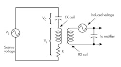
1. The schematic shows how series resonant circuits are used in resonant wireless power coupling.
Series resonant circuits are the most common in wireless chargers (Fig. 1). When XL = XC at resonance, the voltage drops across the ideal inductor and capacitor are equal. Therefore, their effects cancel producing zero opposition to current. In practice, the coil resistance (R) limits the current. It’s the Q of the coil that determines the amount of current produced:
Q = XL /R
XL = 2πfL
The varying magnetic field of the primary coil induces a voltage into the secondary coil. This voltage appears in series with the coil and capacitor, forming a series resonant circuit. The output is taken from the voltage across the capacitor. If the Q is high, a high current flows and the resonance phenomenon produces a resonant voltage step-up across the capacitor. This voltage then goes on to be rectified into dc and used for battery charging. The amount of voltage step-up is given by:
VC = QVs
where VC is the capacitor voltage and Vs is the circuit source voltage; in this case, the induced voltage.
Overall, resonant systems produce higher wattage capabilities and greater efficiency. While the critical physical factor is the placement of the two coils with respect to one another, resonant systems are more tolerant of placement and can work over greater distances than plain inductive chargers.
Wireless Charging
So far, the main use of this inductive power transfer is battery charging. Special circuits and charging products make it possible to charge the batteries in smartphones, watches, and other wearables without a cable. The charging unit, called a charging pad, contains the TX coil and related circuitry and operates from the ac mains. The smartphone or other device contains the RX coil and the battery-charging circuitry. You simply drop the phone on the pad and go.
You must be sure the coils are properly aligned for the best transfer of power. If not, less power is transferred and charging time is longer. Most pads have visual or physical clues to help you place the device in the optimum position.
Another solution is to use multiple TX coils in the charging pad to cover a wider area. These may overlap to ensure that wherever you place the phone on the pad, you will get a good transfer.
One new trend is wireless charging in cars. Multiple auto manufacturers are now building in wireless-charging pads or bins. Currently, most high-end smartphones like the Apple iPhone 8 and X and Samsung Galaxy S8 have integral wireless charging. Some fitness and other watches also contain coils and charging circuits.
The Standards
Early development efforts in wireless charging produced multiple methods and systems. The most widely used standard is called Qi (pronounced “chee”). Developed by the Wireless Power Consortium (WPC), the standard is implemented in chips by multiple semiconductor manufacturers and built into over 200 million smartphones. The WPC tests and certifies Qi-based products to ensure full interoperability between the many Qi products. Here’s a summary of the basic features:
- Three basic power levels: 0 to 5 W, 0 to 15 W, and 0 to 120 W.
- Low-power versions work with coil separation of 5 mm (best when coils are aligned) and a maximum of 40 mm (1.57 in.).
- Frequency of operation: 110 to 205 kHz (typical ~140 kHz). Resonant coupling.
- Data communications link between TX and RX. (RX can inform TX of power needs; RX can inform TX when charging is complete.) Backscatter ASK modulation data link with a rate of 2 kb/s.
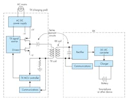
Figure 2 shows a simplified block diagram of a Qi charger and smartphone target.
2. These are the major components of a wireless charging application. The ac mains voltage is converted to dc to power the transmitter (TX) that generates the high-frequency ac applied to the TX coil. The RX coil receives the oscillating magnetic field and produces a signal that’s rectified into dc and used to operate the charger inside the smartphone or other device to be charged. A communications link is provided between RX and TX.
The other major standard is from the AirFuel Alliance, an organization formed by the merger of Alliance for Wireless Power (A4WP) and Power Matters Alliance (PMA) in 2015. While not as widely used, it’s a variation that offers some benefits such as the ability to charge multiple devices simultaneously. AirFuel also tests and certifies devices to for compatibility. Features of its Resonant standard include:
- Six classes of power levels from 2 to 70 W.
- Works with coil separation up to 50 mm (2 in.).
- Frequency of operation: 6.78 MHz. Resonant coupling.
- Greater flexibility in coil alignment and ability to charge multiple devices at a time.
- Data communications link between TX and RX is Bluetooth Low Energy. (RX can inform TX of power needs; RX can inform TX when charging is complete.) Data rate of 1 Mb/s.
Multiple other proprietary technologies exist, but they’re not universal standards. Representative of these is the system of PowerbyProxi, a New Zealand company. Its system is resonant at about 130 kHz, and range is best at less than a centimeter. Backscatter ASK modulation is used for the data communications. Overall, it’s similar to Qi. Apple recently acquired PowerbyProxi, but the Apple iPhone 8 and X use Qi, not the PowerbyProxi standard.
Far-Field Wireless Charging
Only recently has practical RF far-field charging become available. This means charging at some distance more than a few inches. One accepted definition of far field is any distance beyond the following:
Far Field > 2D2/λ
D is the largest dimension of the transmitter or receiver antennas, and wavelength (λ) in meters is λ = 300/fMHz.
Two new systems show what can be done today. First is the long-range system from Powercast Corp. Its PowerSpot transmitter generates a 3-W direct-sequence spread-spectrum (DSSS) signal in the 915-MHz ISM unlicensed band (FCC Part 15).
The signal gets a boost from the 6-dBi gain directional antenna that produces a 70-deg. beam. It creates a charging zone up to 80 feet away, where objects can be placed for recharging without a mat or pad (Fig. 3). The devices to be charged contain the matching Powercast receiver chip that converts the signal into dc for charging.
3. The PowerSpot long-range charger by Powercast creates a charging zone up to 80 feet away, accommodating the charging of multiple devices.
This new system can handle up to about 30 products depending on their requirements. Charge times will vary with distance between devices and transmitter, but generally most devices will charge fully overnight.
Another far-field charging product comes from Energous Corp. Its WattUp system uses the unlicensed 5.85- to 5.875-GHz band (FCC Part 18). The system’s most effective range is from a few inches up to 3 feet, but it can cover up to 15 feet with a weaker signal and longer charging. The 90-deg. beamwidth antenna pattern creates a charging zone into which multiple devices can be placed. Again, the devices must contain the WattUp receivers. Bluetooth Low Energy is used as the link between transmitter and receivers.
For these new far-field systems to catch on, their receivers must be incorporated into the devices to be charged. This may take some time, but the convenience of long-range charging makes them an attractive alternative.
Wireless Charging of Electric Vehicles
One big target for wireless charging is electric vehicles (EVs), and, in fact, a wireless-charging grid is slowly emerging. Today, EV charging is done via heavy-duty cables. But new developments are gradually changing the landscape.
For example, BMW’s and Volkswagen’s electric and hybrid models will eventually incorporate a charging receiver and coil that will match up with a charging pad on the garage floor or in the driveway. Public charging stations would use a similar arrangement. Pad alignment is critical for the fastest and most efficient charging. There’s even a vision of embedding charging pads into roads and at intersections or in parking lots for a quick charge.
An alternative approach to coils is being investigated that uses capacitive coupling instead of magnetic induction. One capacitor plate is located on the bottom of the vehicle and the other plate is on the charger. Capacitive coupling allows higher frequencies to be used. However, plate alignment is critical and movement or changes produce capacitance variations that require active impedance matching to provide an efficient transfer of power.
One company developing automotive chargers is WiTricity Corp. Its patented resonant technology, developed at MIT, is a good fit for EV charging pads. It’s more forgiving of coil alignment and can transfer kilowatts of power efficiently at distances of 10 to 20 cm. It can also penetrate concrete, asphalt, and wood.
Cordless Chargers: An Alternate View
Just what is wrong with cabled chargers? Wireless chargers are cool technology, for sure. And they do offer some convenience. However, they seem to be solving a problem that doesn’t exist. How hard is it to use a wired charger? You just plug it in. We all do it every day, mostly without thinking.
Technology lets us do things that don’t necessarily need doing. We do it because we can. Besides, electronic engineers need continuous challenges. And as it turns out, there are many customers for those cool new products, needed or not. As a result, dozens of companies are now pursuing the complex wireless-charging space.
Here’s a breakdown of the real pros and cons of wireless charging:
PRO
- No messy cables that always seem to get lost.
- Ability to charge multiple devices with one charger instead of the multiple cables usually needed.
CON
- More expensive than a plain old cable charger.
- Charging pads not as portable as a cable.
- Uses more power than a cable charger.
- Careful positioning of the devices on the charger is a nuisance.
- Adds to the growing cloud of EMI.
Despite whatever downsides are perceived, most market projections are rosy. Market research firm Technavio says that the market will grow by more than 33% by 2020. And ABI Research forecasts over 700 million wireless chargeable devices by 2020.


