When a small team made up of Sony and Ericsson developers were working on low-power Internet of Things (IoT) designs, they noticed that the problems they faced when optimizing power consumption were shared by their customers. Once the problems were solved, they packaged the solution, formed Qoitech (as part of Sony), and launched the Otii Arc, an energy-optimization tool that shows exactly where and how energy is being consumed so a design can be optimized.
Designed for developers, by developers, the Otii Arc is now the subject of this special Electronic Design teardown, conducted in partnership with DAC 2018. We go into detail to show the what, why, and how of Qoitech’s design to highlight why the $550 Qoitech Otii Arc energy-optimization system is the perfect blend of hardware and software for any application where power consumption is critical. Think IoT, wearables, and remote sensing. You’ll see why when we cut it open.
The IoT and now machine learning (ML) and artificial intelligence (AI) require the development of an array of low-power, battery-driven devices to supply sensor data from the edge. The typical longevity for these batteries is expected to be 10 years on a single charge. This requires in-depth analysis of every aspect of hardware design and every line of code.
Current tools for analyzing power include multimeters and oscilloscopes. Multimeters are great for getting a bead on the average current consumption. However, they lack the resolution to see fast transients and currents down to the nanoamp range, which is where low-power designs are headed.
For their part, oscilloscopes can be expensive, though used ones are readily available; check the source and ensure they’re calibrated either before or after purchasing. Also, it’s difficult to get access to a trace with a ‘scope, and not all scopes allow display and correlation between executed code and the actual line voltages and signals (Tektronix’s MSO line is good for this, though). There’s also the problem of ensuring the ‘scope has enough memory to store the data.
Moreover, both multimeters and ‘scopes often require the user to pause to adjust the range as currents or voltages rise and fall. For example, it could be 0.5 mA one minute, and 5 A the next for a given IoT device. This can be frustrating when tracking difficult-to-access traces or component inputs and outputs, as often a “third hand” is needed to adjust the scaling.
Otii Arc Melds Hardware and Software
As the developers at Sony were realizing these limitations of traditional test equipment, they did what any good development team would do: They designed their own energy monitoring and optimization solution. The team at the time comprised both hardware designers and software developers from Sony and Ericsson Telecom.
Interestingly, they noted that software developers don’t work too often with physical scopes, with their knobs and buttons, and they also don’t like background noise from system fans. The latter is one of those software-developer quirks. Nonetheless, both aspects, along with the scaling issue, were factored into the design of the Otii Arc, so let’s get into it.
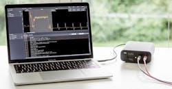
1. The Otii Arc is a power supply that also works with a laptop to serve as an energy optimization analyzer. (Source: Qoitech)
The Otii Arc is a small, portable power supply that also serves as a current and voltage measurement unit, as well as a data-acquisition module (Fig. 1). It connects over USB to a laptop loaded with the accompanying software and runs atop Ubuntu, Windows, and MacOS.
Users can make a one-time purchase of $550 and get the hardware and software, or take out a yearly license for $469/year. This includes the latest software updates and premium support services.
Voltage and current data is sent over the USB connection to the laptop. The Otii can be powered from the laptop USB connection, in which case it will supply 0.5 to 5.0 V dc and 250 mA. Alternatively, there’s a 7- to 9-V dc power input in the rear. With a separate supply, it can supply 2.5 A (continuous) and 5.0 A (peak).
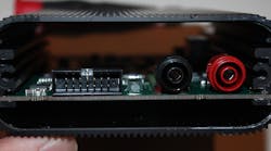
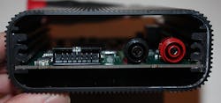
Along with monitoring the current and voltage delivered to the device under test (DUT), the Otii has a 14-pin connector on the front with GPIO pins, another analog-to-digital converter (ADC), +5 V dc and GND, receive and transmit pins, and SENSE pins (Fig. 2). It’s also worth noting that the Otii Arc is also capable of controlling other instruments, over interfaces such as LXI.
2. The 14-pin expansion header includes a +5-V dc supply, GPIO, ADC, GND, receive and transmit pins, and SENSE pins. (Source: ClariTek, LLC)
Next to the header is an LED status indicator, and next to that are the main power banana-plug connectors. In a typical setup to synchronize the DUT with the Otii, the output of the UART on the DUT can be connected to the Rx pin on the Otii. As the DUT executes its code, it’s correlated to the Otii’s power-delivery data and presented together on the laptop GUI.
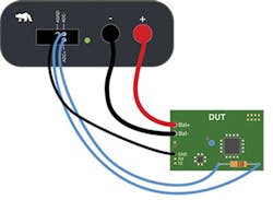
Also, the ADC on the Otii can be connected across a shunt resistor on the DUT to get a view of power consumed in a specific subsection of the design (Fig. 3). It’s wise to place multiple shunt resistors at key locations throughout the design. Once it’s connected to the Otii, set the shunt value in the Otii’s settings and it does the rest, allowing you to tune specific circuits while monitoring overall power consumption.
3. The Otii Arc’s ADC can be connected across a shunt resistor on the DUT to get a view of the power consumed in a specific subsection of the design. (Source: Qoitech)
Key specs of the Otii Arc include a sampling rate of 4 ksamples/s, current resolution down to a few nanoamps, and accuracy of 500 nA +1% down to hundreds of nanoamps and up to 5 A (with averaging).
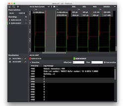
Where the Qoitech software developers really went to work was on creating a GUI that both hardware and software engineers would appreciate. It doesn’t rely on knobs and buttons, with which software developers may not be familiar. Yet it still ensures easy navigation, including scroll and zoom, as well as selection tools to check power consumption at specific time intervals (Fig. 4).
4. The Otii Arc’s GUI is designed for easy navigation and clear presentation of multiple waveforms for comparisons and correlations. (Source: Qoitech)
In addition to synching recordings with debug logs, the software allows comparison of multiple recordings, clearly presents code execution versus current and voltage power measurements, allows for automation with scripting, and even helps choose the right battery for an IoT device.
Inside the Otii Arc
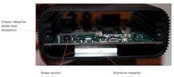
Taking the backplate off exposes the power section and an aluminum block that attaches directly from the power section to the chassis (Fig. 5). The block is a heatsink and the ribbed chassis ensures maximum heat transfer to ambient.
5. Removing the backplate shows the power section, with dc input, USB interface, and the heatsink to pull heat to the ribbed chassis. (Source: ClariTek, LLC)
My first assumption was that the choice of an enclosed, fanless design was for both reliability and minimal noise purposes. However, according to the developers at Qoitech, they know from experience that software developers abhor noisy equipment, so it was mostly about eliminating fan noise.
Question: Are coders generally that sensitive to hardware noise? Let me know using the comments section below.
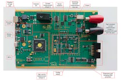
Sliding the board out, Qoitech helped identify the key sections of the design (Fig. 6). There are two main aspects to look at here. The first is the circuitry that automatically switches between ranges (Range 1, 2, and 3). Used with the three sense resistors at the center of the board, this is the circuitry responsible for allowing the Otii Arc to switch automatically between ranges.
6. The current measurement range circuitry (Ranges 1, 2, and 3) does the automatic range switching, while the perforations keep the sensitive analog circuits isolated from on-board heat sources. (Source: Qoitech)
Also, note the perforations at the center of the board. These help keep the sensitive analog circuits isolated from heat generated by other board components.
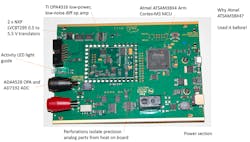
The precision analog components include the Analog Devices ADA4528 ultra-low-noise, zero-drift op amp and the company's AD7192 4.8-kHz, ultra-low-noise, 24-bit, sigma-delta ADC with programmable gain amplifier (PGA) (Fig. 7). The AD7192’s noise is specified at 11 nV at 47 Hz, with a gain of 128. ADI emphasizes low drift in its precision parts, and the ADA4528 and AD7192 are no exception, with an offset drift of 0.015 µV/˚C (maximum) and 5 nV/˚C, respectively.
7. Key components on the main board include the Atmel ATSAM38X4 Arm MCU and the precision analog components from Analog Devices. (Source: ClariTek, LLC)
Also shown in the analog section is the Texas Instruments 10-MHz OPA4316 low-power, low-noise, differential op amp.
The main processor on the board is an Atmel ATSAM3X8E Arm Cortex-M3 MCU. It was chosen mainly because designers were familiar with it, and in which they had a lot of software investment. Also on the board are two NXP LVC8T245 level translators.
User Feedback
According to Qoitech, the user community has been positive about the Otii Arc, particularly with its ease of use, low cost, and the fact that it supports three OS platforms. In May, Qoitech announced a major software upgrade to Release 2.00. Let us know if your experience with it!
