5G is approaching rapidly, with the first deployments expected in 2019. Initially, mobile operators are targeting specific applications where they see considerable potential demand and opportunity.
However, 5G will expand the global uses of wireless communications. A second wave of applications in 2020 and beyond will include automotive communications, home automation, virtual reality, and potentially millimeter-wave (mmWave) smartphones. Meanwhile, 4G will continue to be enhanced and remain the mainstay of cellular connectivity for many years, even as 5G provides higher data rates and new services.
Two key early 5G applications are enhanced mobile broadband (eMBB) and fixed wireless access (FWA). eMBB will deliver multi-gigabit data rates to smartphones, initially using sub-6-GHz frequencies. FWA will compete with cable and fiber services to deliver high-speed connectivity to homes and offices, and represent the first widespread use of mmWave frequencies for consumer cellular applications.
Standards Progress
The initial set of 5G NR specifications, delivered in draft form in December 2017 in the first phase of 3GPP Release 15, was published in June 2018. The specifications focus on mobile deployments using the non-standalone (NSA) 5G New Radio (NR). NSA uses an LTE anchor band for control, together with a 5G NR band to deliver faster data rates. This lets operators deliver 5G speeds more quickly and at lower cost by extending their existing LTE networks, without needing to build out a whole new 5G core.
5G standalone (SA) NR draft specifications are currently due for delivery by the end of 2018. SA removes the need for an LTE anchor and requires a full 5G network buildout.
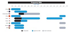
3GPP has also defined new and refarmed bands in two frequency ranges. Frequency Range 1 (FR1) covers sub-6-GHz frequencies, including new bands above 3 GHz such as n77, n78, and n79 (Fig. 1), plus refarmed LTE bands such as n41. Frequency Range 2 (FR2) currently includes mmWave bands between 24 GHz and 39 GHz (n257, n258, and n260).
1. Regional allocations for sub-6-GHz frequencies (FR1).
RF Challenges
As with any major advance in communications technology, 5G presents a whole new set of technical RF challenges. These include:
- Unprecedented bandwidth, with carriers up to 100 MHz wide in FR1 and 400 MHz in FR2.
- Massive MIMO and beamsteering will be required in base stations to deliver multi-gigabit data rates.
- Massive bandwidth and new waveforms will generate very high peak-to-power ratios and a need for high linearity.
There are also significant commercial challenges with 5G, due to the cost of upgrading infrastructure and user equipment. Manufacturers and operators will need to balance the cost and complexity of adding 5G RF content against the performance benefits. Those considerations will factor into their technology choices.
Mobile Deployments in Sub-6-GHz Spectrum
With early mobile deployments expected as soon as 2019, handset makers are under pressure to add 5G RF content to phones even as the specifications are still being finalized. This presents several challenges.
For example, 5G specifications stipulate that handsets must support four downlink paths for bands above 1 GHz, to enable higher data rates. This requires four antennas and four independent RF pathways. For many handsets, the change will mean a substantial increase in RF content, signal-routing complexity, and antenna bandwidth. It will be challenging to squeeze even more content into already-crowded space allocated to the RF front end, and highly integrated solutions will be needed to minimize solution size and increase performance.
Antenna tuning will become even more important to keep the total number of antennas within manageable limits. In addition, increased signal-routing complexity will require the use of antenna-plexers that maximize the number of signal connections while maintaining low insertion loss.
Dual Connectivity Multiplies RF Interference Challenges
Most initial eMBB deployments in the U.S., and some other countries, will use 5G NSA. This adds significant complexity because it requires dual 4G LTE and 5G connectivity. NSA will continue to present challenges for handset RF design over at least the next decade, until all mobile operators convert to SA.
Dual connectively can create extremely complex challenges. For example, new NSA carrier-aggregation combinations use multiple 4G FDD-LTE anchor bands together with a 5G band. The NSA specification also allows the handset to transmit on one or more LTE bands while receiving on the 5G band.
An example is the aggregation of LTE bands 1, 3, 7, and 20 with 5G band n78. Because n78 occupies a much higher frequency range than the LTE bands (3.3-3.8 GHz) and is extremely wide, there’s much greater potential for harmonic frequencies generated during LTE transmissions to fall into the n78 frequency range, potentially causing receiver desense. However, the RF filtering needed to achieve the requisite attenuation can lead to increased insertion loss, requiring higher PA output power.
Higher Bandwidth, New Waveform
FR1 bands provide unprecedented single-carrier bandwidth up to 100 MHz, five times the LTE maximum of 20 MHz. While this is critical for multi-gigabit data rates, it also produces power-management challenges. Today’s flagship LTE handsets use envelope tracking (ET) to minimize power consumption, but envelope trackers are only expected to support up to 60-MHz bandwidth at the time of 5G deployments. Because of this, PAs will need to operate in average-power-tracking (APT) fixed-voltage mode when supporting wideband 5G transmission, reducing efficiency.
The new 5G waveform, CP-OFDM, provides very high spectral packing efficiency and good MIMO support. However, the higher peak-to-average power ratios (PARs), together with massive bandwidth, require greater PA backoff to stay within regulatory limits and maintain linearity. This potentially reduces the efficiency of the Tx chain and creates a challenging high linear power requirement for PA design.
Massive MIMO in Mobile Infrastructure
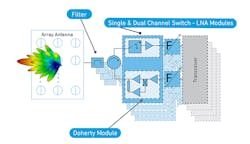
To deliver multi-gigabit data rates, 5G base stations will use massive MIMO with large antenna arrays. These active antenna systems (AAS) enable beamforming and beamsteering, creating highly directional antenna beams that can be redirected in less than a microsecond to deliver higher data rates to specific locations or devices.
2. Massive-MIMO architecture for sub-6-GHz 5G infrastructure.
For sub-6-GHz systems, current designs typically use 32 to 128 array elements, depending on the effective isotropic radiated power (EIRP) required (Fig. 2). Due to the large number of array elements and the output power required from each element, thermal dissipation becomes a critical challenge, driving designs toward technologies that provide the highest possible efficiency.
Another RF challenge is that multiple FR1 bands exist at frequencies ranging from 3.3 GHz up to 4.9 GHz (Fig. 1, again). With this increase in frequency, performance of historically used RF power technologies begins to diminish. For instance, both transistor gain and efficiency, which are interrelated, start to suffer with silicon-based power technologies such as LDMOS in the transmit path. LDMOS has compelling performance at 2.5 GHz, but at 4.9 GHz, technologies such as gallium nitride (GaN) sets itself apart, and we’re seeing that in the marketplace today.
Base-station architectures must also manage the risk that a Tx signal will feed into the Rx chain, damaging sensitive components like the LNA. This requires a switch capable of driving high-power signals to a load. The challenge is minimizing insertion loss and the resulting increase in the Rx chain noise figure, while maximizing power handling in an integrated module.
Fixed Wireless Access: Moving up to mmWave
The goal of FWA is to deliver gigabit data rates wirelessly to buildings in a fraction of the time and cost of traditional cable and fiber installations. Mobile operators in the U.S. see FWA as a major opportunity, with some aiming for early deployments in 2019.
For operators, a key advantage of mmWave frequencies is that vast amounts of licensed spectrum are available at low cost. 5G mmWave bands also support component carriers up to 400 MHz, even wider than in FR1.
However, path loss at mmWave frequencies presents a key challenge; obstacles such as vegetation, walls and even glass, as well as interference in urban environments, have a significant effect. To compensate, FWA infrastructure will use large antenna arrays and high output power (Fig. 3). Current base-station designs under consideration range from 64 to 1024 elements, depending on the technologies used, with a typical target of 65-dBm EIRP.
3. Massive-MIMO hybrid-beamforming architecture for 5G mmWave fixed wireless access.
The challenge is to achieve the required output power and beamforming gain while minimizing power consumption. Antenna arrays must be power-efficient to allow for passive cooling, a requirement for electronics installed on cell towers. It’s difficult to dissipate more than 300 W from the RF subsystem.
Among the approaches being considered is a hybrid beamforming architecture using a silicon-germanium (SiGe) BiCMOS beamformer and front end. Due to the limited power density of SiGe, this could require a very large array of up to 1024 elements or more, which would then exceed base-station power-consumption and power-dissipation limits. Such a large array also adds considerable signal-routing complexity.
An alternative architecture, also using hybrid beamforming, combines a silicon-based beamformer with a GaN RF front end. Because GaN offers much higher power density, it enables smaller, more efficient high-power PAs. Using GaN PAs potentially requires an array of only 64 elements to achieve the same EIRP, which could reduce cost by 80% and use 40% less power.
Mobile mmWave
Further into the future, mmWave infrastructure designs may also be extended to support mmWave in handsets. However, mmWave in handsets is investigational at this stage. It involves the considerable challenge of building antenna arrays and other required RF content into smartphones.
A big question is whether the benefit to users will justify the cost and complexity, given the anticipated availability of other short-range options such as offloading traffic to unlicensed Wi-Fi spectrum.
Mobile mmWave is initially expected to appear in nomadic devices, such as portable hotspots. It has the potential to gain traction in handsets after 2020, too.
Conclusion
As with any major advance in communications, 5G presents significant RF challenges for mobile devices and infrastructure, and will require innovative new solutions. When making technology choices, the cost and complexity of adding 5G content will be weighed against the performance benefits.
Ben Thomas is Director of Technical Marketing, and Scott Vasquez is a Senior Market Strategy Manager for Infrastructure and Defense Products at Qorvo Inc.


