Download this article in PDF format.
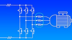
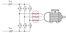
Accurately measuring current flow is a standard requirement in several applications (Fig. 1). Depending on the specific need, the options available to designers can include discrete designs assembled from standard components, application-specific devices, and ready-made solutions embedded into another block such as a microcontroller or system-on-chip (SoC) device. In this article, we’ll look at some of these approaches, their advantages and disadvantages, and how to make the best use of them in a design.
1. Measuring current is a key part of many industrial operations, such as this three-phase motor controller.
Sponsored Resources:
- Using current sense amplifiers to solve current sensing design challenges
- Precision current measurements on high-voltage power-supply rails
- Current Sensing: External current sense amplifiers versus integrated onboard amplifiers
Introduction to Standard Current-Sensing Techniques
The standard technique for measuring current through a load is to add a low-value sense resistor (also called a shunt resistor) in series and measure the resulting voltage across the resistor; the voltage is proportional to the current.
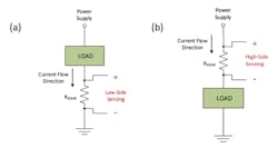
As shown in Figure 2, there are two locations for the sense resistor. Low-side sensing places it in the return path from the load to ground. The device requirements for low-side sensing are minimal, requiring only an amplifier capable of handling a common-mode signal reaching down to ground. Many types of operational amplifiers (op amps), including standard products, difference amplifiers, instrumentation amplifiers, and current-sensing amplifiers, have this feature.
2. Low-side (a) and high-side (b) current-sensing schemes each have strengths and weaknesses.
One of the drawbacks to low-side sensing is that the load no longer has a direct connection to ground. Instead, the low side of the load is raised above ground by a variable amount depending on the current flowing through the sense resistor.
As shown in Figure 2a, when current passes through the shunt resistor, the voltage developed across the component changes, causing the system reference to deviate from the ground potential of the monitored load. This varying reference connection can cause problems if the system isn’t able to accommodate the ground potential shifting in proportion to the system current. In addition, a shorted shunt resistor can’t be detected as the measured voltage is zero—indistinguishable from no current flow.
Alternatively, the shunt resistor can be placed on the high side of the load (Fig. 2b). The location between the power rail being monitored and the rest of the circuit avoids both the varying system reference and shorted shunt detection issues of low-side current measurement.
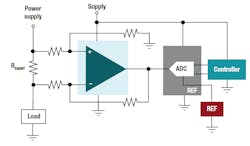
One challenge associated with the high-side measurement location is that the amplifier must interface with large input-voltage rails, such as high-voltage batteries. A typical current-measurement signal chain (Fig. 3) amplifies the voltage across the sense resistor and then sends it to an analog-to-digital converter (ADC). In many applications—communications and industrial equipment, for example—the input range of the ADC (whether discrete or integrated into a microcontroller) is relatively small compared to the voltage rails being monitored. Common-mode voltage requirements can exceed 60 V, requiring the amplifier to handle input signals far exceeding the allowable input range for the low-voltage component.
3. A typical signal chain for a high-side current-sensing application.
Choosing the Correct Components is Key to Success
A discrete current-sense circuit offers the opportunity to optimize the design. In this case, how can we maximize the accuracy of the current measurement?
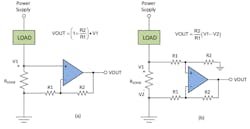
Figure 4 shows two circuit options for a low-side sensing circuit. Option (a) measures V1 at the positive input using the standard non-inverting op-amp configuration. Only two resistors are needed, but the circuit output VOUT only depends on V1 and doesn’t sense the ground side of RSENSE. This can result in errors if the low side of RSENSE rises above ground; for example, if RSENSE has a low value or there’s a high ground current.
4. Two options for a discrete low-side current-sense design.
Option (b) uses the classic difference amplifier topology to sense the voltage drop across RSENSE directly. This method gives a higher level of accuracy, especially when higher currents are sensed, as it accounts for any voltage drops from RSENSE to the PCB ground.
For correct operation of option (b), the R1 and R2 pairs must match each other precisely. Any mismatch in resistance values creates a measurement error. Resistors with ±1% tolerance can give a cumulative error of up to 2%. The resistor temperature coefficients can typically range from tens of ppm/°C to hundreds of ppm/°C, constituting an additional potential source of error. The resistance of a 200-ppm/°C resistor can drift by as much as ±1% with a 50° temperature change.
Another factor to consider is the PCB layout. The gain resistors must be placed as closely as possible to both the op amp and RSENSE to reduce the potential for noise pickup on the op-amp input pins. The traces that carry the current should not be used for monitoring purposes. Instead, a separate pair of traces should be added that connects the sense resistor to the current-sense amplifier inputs. This four-wire Kelvin connection yields the best results.
The designer must also ensure that the current-sense circuit doesn’t pick up radiated noise from other circuit blocks, in particular switching noise from dc-dc converters.
Op-Amp Considerations
Moving on to the op amp, it’s important to scrutinize the datasheet to make sure the device you’re mulling over can meet the needs of a current-sense design. Consider a popular general-purpose op amp such as the LM321. This device has an input offset voltage as high as 7 mV—this is a problem in a current-sensing application that must accurately measure a small differential voltage. A 7-mV offset represents a 7% measurement error in a 100-mV signal.
Reducing the measurement error requires an increase in the differential signal; i.e., increasing the value of the sense resistor RSENSE. A larger-value sense resistor will dissipate more power. Therefore, it must be a larger, more expensive, higher-wattage component.
The LM321 also has a slew rate of 0.4 V/µs and a gain bandwidth (GBW) product of 1 MHz. When configured as a current-sense amplifier with a gain of 20, the bandwidth is reduced to approximately 50 kHz. The low bandwidth and slew rate make the LM321 a poor choice in applications with fast current signals or those that require fast detection of overcurrent conditions. The limitations of the output swing and input common-mode range also restrict the areas in which the device can operate. For instance, if the output of the current-sense amplifier is driving a lower-voltage ADC.
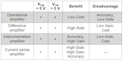
Figure 5 shows the relative strengths and weaknesses of different op-amp topologies for current sensing. Manufacturers offer various specialized devices to help designers with some of the challenges discussed earlier.
5. A comparison of amplifier types for current sensing.
Integrating the gain resistors and the op amp into a single-package difference amplifier is one option. Placing the resistors on-chip brings important benefits that include increased matching and temperature drift stability compared to external components.
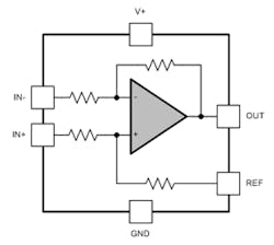
Many difference amplifiers in Texas Instruments’ portfolio feature a wide common-mode range for both high-side and low-side sensing. The configuration shown in Figure 6 is common; one of the gain resistor terminals is pinned out to the REF pin. For a unidirectional current, this is commonly grounded. Connecting it to a reference voltage adds a dc offset that allows the device to monitor bidirectional currents.
6. Many TI difference amplifiers include a REF pin to monitor bidirectional current flows.
A standard difference amplifier can be used to sense current, but most difference amplifiers are unity-gain devices and require an extra gain stage in this application.
Getting a Sense of Current-Sense Amps
A current-sense amplifier is a difference amplifier plus gain. The INA21x, for example, is a family of dedicated current-sense amplifiers suitable for applications including cell phones, notebook computers, and battery chargers. The device family supports both low-side and high-side current sensing and offers a choice of six fixed gains, from 50 to 1000 V/V. For space-constrained applications, the INA21x is available in a quad flat no-lead (QFN) package measuring only 1.80 × 1.40 mm.
Standard current-sense amplifiers are often available in single, dual, and quad versions for such applications as monitoring the currents in multiple power rails or monitoring both high and low sides of a load to detect leakage current paths. Other devices provide additional functionality: The INA381, for example, includes a latching comparator that provides an alert when the sense-resistor current exceeds a predetermined threshold, and the INA190 features an enable pin that allows the device to be placed in sleep mode. The INA190 draws extremely low current while asleep, making it ideal for battery-powered applications.
The INA253 even includes a 2-mΩ shunt resistor. It offers a choice of three fixed gains, and is designed to monitor bidirectional currents over a common-mode range from –4 to +80 V. Applications for the part include solenoid and valve controls; motor controls; dc-dc converters; transmission control; and Class-D audio amplifiers.
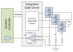
In many applications, the current-sense circuit is included in a larger system block. Figure 7 shows one such application: a power block for an industrial three-phase motor, consisting of three H-bridge power drivers controlled by an integrated gate-driver block that includes current-sense circuits to measure the phase currents.
7. System blocks such as this integrated three-phase gate driver often include the current-sense circuitry.
Many three-phase gate drivers include current sensing as a standard feature. Integrating the measurement circuitry can result in a simpler design with fewer components than a discrete approach composed of multiple single-function devices. This approach is particularly popular in portable and battery-powered applications such as power tools, which have limited space available for the electronics.
One drawback to this approach is the limited ability to optimize the measurement accuracy. Also, the silicon process technology of the power blocks is typically designed for highest efficiency in the power blocks: regulators, switching power supplies, power transistors, etc. The design tradeoffs necessary to achieve such a goal may limit the performance of the precision analog blocks on the chip.
Further Information
Texas Instruments offers multiple resources for designers of current-sense amplifiers. A good place to start is the current-sense solutions overview page. Also see the video series, “Getting Started with Current Sense Amplifiers.” This 16-part series focuses on how to get the most out of your current-sense amplifier design and includes an in-depth discussion of error sources.
Sponsored Resources:
- Using current sense amplifiers to solve current sensing design challenges
- Precision current measurements on high-voltage power-supply rails
- Current Sensing: External current sense amplifiers versus integrated onboard amplifiers
Related Resource:
