Download this article in PDF format.
Your ability to connect more higher-power devices to your Ethernet LAN just got better. Last year, the IEEE’s 802.3bt standard was approved, significantly boosting the power available to connected devices. Now, new products are emerging to take advantage of this improved resource. If you’re working on products for Ethernet connection, ON Semiconductor offers some new devices that can facilitate your job.
Sponsored Resources:
- IEEE 802.3bt PoE PD Reference Design
- Quad MOSFET Approach Delivers Dramatic PoE Efficiency Improvements
- 11 Myths about PoE
A Little Background
It seems like most of the devices and equipment we use daily are wireless. Wireless is everywhere, from cellular to Wi-Fi, Bluetooth and others. But that wireless trend hasn’t replaced wired networks. The most common examples are the thousands or more Ethernet networks that connect servers to Wi-Fi access points, PCs, VoIP phones, and IP cameras.
Virtually every office building and other workspaces are pre-wired for Ethernet. Factories have continued to adopt Ethernet for a wide range of industrial applications. A recent development is the inclusion of a special version of Ethernet for automotive equipment networking.
Ethernet still provides a reliable, secure, and flexible backbone to many facilities. One good new application is to use Ethernet and Power over Ethernet (PoE) in your Internet of Things (IoT) projects. Sensors, actuators, and other devices must communicate with some gateway to send or receive data. What better way than Ethernet? Furthermore, these IoT devices all require power. PoE can eliminate the need for battery or separate AC power. Think about it—who says that wired Ethernet is retro?
The PoE standard lets you deliver dc power to end devices while simultaneously transmitting data at the usual speeds, eliminating the need for an ac power-line connection at the connected device. The IEEE standard 802.3af was introduced in 2003. It specified a maximum available power of 15.4 W for each port, but only 12.95 W is guaranteed. Power for end-connected devices was typically delivered via ports on an Ethernet switch.
Users quickly discovered that the port outputs could not always provide the needed power. One example of this is IP surveillance cameras. In 2009, the IEEE issued an upgrade called PoE Plus and a new standard designation 802.1at. That boosted the power available per port to 25.5 W.
Additional enhancements continued with the 802.3bu standard in 2016, which provided dc power over a single-pair twisted pair defined for those new industrial and automotive Ethernet versions. In 2018, the 802.3bt standard was introduced. It offers new types of configurations that further boosted power levels to 55 W and 90 to 100 W.
Remember, the dc voltage and current is carried over standard Ethernet cable, still mostly CAT5, but CAT6 as well. Most of these cables contain four twisted pair. Data speeds can be 10 Mb/s, 100 Mb/s, and 1000 Mb/s (1 Gb/s). The 100- and 1000-Mb/s versions are the most common, with the newer 2.5- and 5-Gb/s options growing in usage.
The exact configurations for how the voltages and currents are connected for each standard vary widely. Standard RJ-45 connectors continue to be used, but wiring varies considerably. The increased power capability and resulting high current is handled by using all four UTP pairs in parallel. See the IEEE standards publications for details.
Some Design Considerations
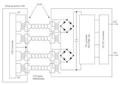
In PoE terminology, the product supplying the power is called the power sourcing equipment (PSE) and the item to be powered is designated the powered device (PD). Figure 1 shows the general arrangement.
1. Here’s a simplified presentation of the PSE-PD connections via Ethernet. The dc power from the PSE travels over the unshielded twisted pair (UTP) to the PD, where it powers a controller and a dc-dc converter that operates the PD end equipment.
The PSE puts the dc power on the cable by way of the transformers that are commonly used to couple the data to the cable. The dc connections vary with the standard. The cable connects to the PD and the data and dc power via the interface transformers. The differential data lines go to the internal processing circuits. The PD controller works with the PSE controller to set up the service. The PD controller may also have an internal dc-dc converter or the control functions to implement one.
A special consideration is given to the dc. It’s the DC input that’s usually connected through a passive circuit to ensure that the dc polarity is correct. This is most often implemented with a diode bridge. Regardless of the input polarity, the bridge manipulates it to the polarity needed for this PD. The dc goes on to power a dc-dc converter that supplies the operating voltage for the product.
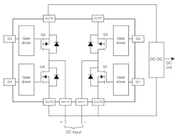
As it turns out, that diode bridge consumes a great deal of power because of its high forward-voltage drops. That problem can be resolved with one of ON Semi’s products—the Fairchild MDMQ8205, a four-MOSFET bridge that offers much lower conduction losses than the usual Schottky diode bridge (Fig. 2). This IC is one of several MOSFET bridges from the company’s GreenBridge series. External circuits provide the gate-drive signals to turn the MOSFETs off and on. Different versions of this device are available for different voltage and current levels.
2. The FDMQ8201 quad MOSFET bridge IC, with its lower losses, is used in place of a standard diode bridge for polarity protection.
Designing PoE Equipment
If you’re designing a PoE PD, you will need an interface to the Ethernet cable and a controller for a dc-dc converter to power the PD circuits. The amount of power to be consumed by the PD determines its class. The 802.3bt standard defines eight power classes from 4 W (Class 1) to 90 W (Class 8). The PSE detects a connected PD and then interrogates it. The PD requests a specific class, which the PSE is configured to provide.
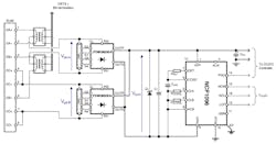
Figure 3 shows one possible configuration, which uses an ON Semiconductor NCP1096 PD interface controller. It supports the latest 802.3bt standard and can handle up to the maximum power level Class 8. Note that the FDMQ8203 quad MOSFET bridges are used instead of the usual lossy diode bridges.
3. Shown is a common PD implementation using a NCP1096 controller.
If you would like to implement an IEEE 802.3bt PoE Class 8 PD reference design to expedite your development, it can be done by combining an ON Semi IEEE 802.3bt PoE−PD evaluation board (EVB) and an active-clamp forward-converter EVB based on the NCP1566. The NCP1566TELECGEVB board is designed to quickly assess the NCP1566, a highly integrated dual-mode active-clamp PWM controller targeting small- to medium-power-level isolated dc-dc converters for use in telecom and datacom industries.
Myths about PoE
Ethernet may seem like yesterday’s technology. However, it will even be crucial in the delivery of 5G services, thanks to the latest iteration of the specification, which boosts the total power available over a single connection to 90 W. If you’re working on some PoE equipment, you really do need a copy of the official standard, the IEEE 802.bt-2018, which is available at the ANSI site.
Sponsored Resources:
- IEEE 802.3bt PoE PD Reference Design
- Quad MOSFET Approach Delivers Dramatic PoE Efficiency Improvements
- 11 Myths about PoE
Related Resource:


