Transforming Electric Vehicles: The Doubly-Fed SYNCHRO-SYM Motor (Part 1)
Members can download this article in PDF format.
What you’ll learn:
- An introduction to the symmetric, multiphase, wound-rotor “synchronous” doubly-fed motor or generator system, called SYNCHRO-SYM.
- How SYNCHRO-SYM is only possible with brushless, automatic, sensor-less, real-time emulation control (BRTEC).
- How SYNCHRO-SYM will double the power rating and octuple the peak torque rating at half the cost and loss per unit of power rating of any other electric motor system package.
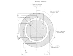
The classic study of electric motor and generator (EM) theory always begins with the cross-sectional view of a smooth air-gap, radial-flux rotating electric machine (i.e., electric motor, generator, or transformer). It has the analytical simplicity of a single-turn, two-phase, distributed winding set symmetrically placed on the rotor and stator, respectively, without altering the size, cost, and loss of the typical EM package footprint (Fig. 1).
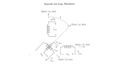
Figure 2 is the schematic representation of Figure 1, It results in the balanced electromagnetic flux relationships of Figure 3 when hypothetically and brushlessly excited with the multiphase currents shown in Figure 4 that precisely satisfy synchronous operation at any speed (i.e., 0 = ±ws ±wr ±wm, where wm (or θ = wmt + θm) is the mechanical angular speed of the shaft). Voltage at the winding terminals is the time derivative of flux.
We’ll see that Figure 1 is the basic element of SYNCHRO-SYM. Because only a directly excited multiphase winding set (or active winding set) independently produces a rotating magnetic flux that pushes or pulls on its rotor or stator frame, only an active winding set determines the rated torque of the EM and both active winding sets of the rotor and stator assemblies (i.e., doubly-fed) contribute active power to the electromechanical energy-conversion process.
The classic study of EM theory ends with the study for any other EM by deoptimizing the symmetry of rotor and stator active winding sets with the asymmetry of:
- A passive rotor with either a slip-induction winding set (i.e., asynchronous or slip-induction EM), reluctance saliences (i.e., synchronous or asynchronous reluctance EM), permanent magnets (i.e., synchronous rare-earth permanent magnet EM), or a DC field winding (i.e., synchronous wound-rotor EM).
- An active stator (i.e., singly-fed) with the universally essential active winding set as found on any EM for developing torque and power rating. Without a directly excited active winding set, the passive rotor can’t independently contribute additional working power to electromechanical energy conversion process.
For example, permanent magnets and reluctance saliencies have no electrical power port for energy conversion, the DC field winding isn’t multiphase and can’t develop a rotating flux in relation to its frame, and a slip-induction winding set is mutually coupled but a passive extension of the stator active winding set.
Best Electric Machine (BEM) conveniently categorized any EM as either an asymmetric EM (AEM), which has a “passive rotor” of a slip-induction winding set, reluctance saliencies, DC field windings, or permanent magnets, or a symmetric EM (SEM), which has an “active rotor” with another directly excited multiphase winding set.
Exploring EM Electronic Control: What is BRTEC?
For practical operation (e.g., the reluctance or permanent magnet EM), for optimum performance (e.g., the induction EM), or for variable-speed operation, the EM needs electronic frequency and voltage excitation control at the terminals of the active winding set(s) or a gearbox to match the speed of the EM to the speed of the load. As a result, the EM becomes an electric machine system (EMS).
Since the electronic controller or gearbox is essential to the EMS performance as actually applied, their compounding loss, cost, and size should be equitably included in the total loss, cost, and size of the applied EMS. Also, for useful torque production, the port excitation frequency and voltage must be synchronized to the speed and phase of the rotor and the back EMF of the active winding set(s).
That’s a complex feedback control function typically provided by a state-of-art derivative of field-oriented control (FOC) or direct-torque control (DTC) with the adverse estimations and delays of offline processing/ This is particularly the case when the slope of the speed, frequency, current, or voltage signals is too shallow to timely or accurately measure or synthesize.
Since the AEMS only operates at synchronous speed, such as the permanent magnet (PM) AEMS, or at a small slip speed below synchronous speeds with inherently negative shaft feedback response, such as the asynchronous or slip-induction AEMS, FOC and DTC are adequate for operational stability.
In contrast, the classic study of the SEM conceptually hypothesized the invention of an extraordinary brushless, real-time (i.e., instantaneous) emulation (i.e., sensor-less and automatic) control means (BRTEC) to guarantee contiguously stable and controllable “synchronous” operation from sub-synchronous to super-synchronous speeds. Such cases include:
- Where control signal slopes are too shallow to be timely or accurately measured or synthesized by FOC or DTC.
- Where random rotor shaft or line perturbations cause unstable oscillations that are further aggravated by the untimely or estimated feedback response of FOC or DTC, introducing insidious slip-induction (or asynchronous) components to synchronous operation.
- Where operational reliance on slip-induction ceases to exist, such as at or about synchronous speed.
Because of the formidable challenges of a practical BRTEC invention to guarantee stability, the SEMS has been left to antiquity. Any contemporary research seems to repeat the early pioneering SEMS research (circa 1960), which already concluded the need for a practical BRTEC means.
Consequently, without an experienced understanding, the symmetric circuit and control architecture of the SEMS is always confused with the asymmetric circuit and control architecture of the so-called “induction” doubly-fed AEMS. The latter is known to be discontinuous and unstable without wasteful rotational damping, such as found with the popular, doubly-fed generators of today’s wind turbine.
Symmetric vs. Asymmetric: EMS Comparison Criteria
The following must be understood to recognize an equitable qualitative comparison between any AEMS and the SEMS:
1. Except for the ultra-high magnetizing MMF and resulting air-gap flux density potential of the superconductor or so-called super permanent-magnet AEMS, or the low air-gap flux density potential of the so-called coreless or non-RE-PM AEMS (e.g., the ferrite PM AEMS), the EM air-gap flux density is constrained by the flux saturation limit and permeability of the magnetic core. It’s not constrained by the residual flux density limit of the rare-earth permanent magnet (RE-PM), which is non-ideally proportional to the inverse of coercivity, or the higher air-gap flux density potential of an electromagnet, which is ideally proportional to magnetizing MMF (e.g., coercivity). As a result, an “optimally designed” EM with the same performing magnetic core should have similar air-gap flux density.
With similar air-gap flux density, any EM with an “optimally designed” active winding set(s) will have similar air-gap area for the same torque, voltage, frequency of excitation at synchronous speed, and pole-pair count design, which includes the optimized placement of slots for the winding sets or permanent magnets. For similar air-gap area, particularly in an axial-flux form factor with similar adjacent disks, an “optimally designed” EM will have similar volume, when including all enabling components, such a structural frame, bearing, endplates, back-iron, and fan, regardless of the potentially shallower material depth of RE-PMs.
2. A parametric design baseline must be established, such as comparing against the same voltage, pole-pair count, continuous torque rating at synchronous speed, frequency of excitation at synchronous speed, and thermal management of the universally essential active winding set(s).
For example, indiscriminately raising the active winding set port voltage of one EMS contestant without allowing the same opportunity to other EMS contestants, or without combining the compounding loss, cost, and size of the voltage raising components, such as a voltage step-up transformer, invalidates the comparison.
3. Including all of the critical enabling components of the stator assembly (e.g., the active winding set, magnetic core, and structural frame), as well as the rotor assembly (e.g., the magnetic core, structural frame, bearings, thermal management such as the fan, and end plates), and the active winding set, slip-induction winding set, permanent magnets, reluctance saliences, or dc field winding, the stator or rotor assembly reasonably consumes half of the total size, cost, and loss, which includes windage and core loss, of the EMS.
4. Rarely the case, the compounding loss, cost, and size of the enabling electronic controller or gearbox should be equitably included, when comparing any EMS as actually applied.
It follows that any extraordinary performance difference between AEMS contestants is the result of differently applying readily available material, winding, electronic component, thermal management, or packaging design techniques.
Extraordinary Attributes of the SEMS
By stably and contiguously operating from sub-synchronous speed (including zero speed) to super-synchronous speed (including at or about synchronous speed) as only possible with BRTEC, the symmetric circuit and control architecture of the SEMS provides double the constant-torque speed range as the AEMS for a given frequency, voltage, pole-pair count, torque, and packaging (i.e., 7,200 rpm with 60 Hz and one pole-pair for the SEMS versus 3,600 rpm for the AEMS). That’s tantamount to twice the power density.
Further backed up by prototyping and BEM-CAD, a century of classic electric motor and generator study, research, and publication theoretically proved:
- The SEMS shows twice the power density of the AEMS per unit of continuous EM package power rating by combining the power of two similarly rated active winding sets on the rotor and stator, respectively, versus the power of the same rated single active winding set on the stator alone.
- The SEMS shows half the total electrical loss (and heat dissipation) of the AEMS per unit of continuous EM package power rating. That’s because for the total power rating (V × Itotal) of the SEMS, only half of the total current (I) is applied to the terminals of the rotor or stator active winding set with the same voltage (V) through a half-current-rated electronic controller (i.e., with total electrical loss defined as Itotal2R, the rotor loss of (Itotal/2)2R or Itotal2R/4 plus the stator loss of Itotal2R/4 equals Itotal2R/2 or half the Itotal2R power of the AEMS).
- The SEMS shows at least octuple the peak torque of the AEMS per unit of continuous EM package power rating. That’s because, in accordance with the EM physics of a dual ported (or symmetric) transformer topology, the torque MMF or magnetic flux on each side of the air-gap of the SEMS is neutralized in the same manner as conservation of energy. As a result, peak torque current can increase without leading to core saturation or permanent magnet damage that’s experienced by the AEMS.
- The SEMS shows up to half the cost of the AEMS per unit of continuous EM package power rating. With the simplest BRTEC configuration controlling only the rotor winding set, the SEMS provides twice the power rating with the same packaging and same amount of enabling system materials and components, such as electronics, as the AEMS.
- The SEMS shows similar core loss as the RE-PM AEMS per unit of continuous EM package power rating. The reason is the SEMS provides twice the power rating with the same amount of magnetic core material in the same changing magnetic flux path as the AEMS. That’s tantamount to half the core loss as the AEMS with a reluctance or slip-induction rotor, or similar core loss to that of the RE-PM AEMS with a passive permanent magnet rotor.
- The SEMS is without the cost, environmental, forced labor, and geopolitical consequences of RE-PMs.
- The SEMS inherently and optimally provides the coveted attribute of field weakening to improve performance and extend speed range. Ironically, it’s being non-optimally re-introduced into today’s highest performing RE-PM AEMS with the loss, cost, and size of magnetizing MMF that was the original motivating factor for migrating to the RE-PM AEMS from the induction AEMS.
- As the classic 101 study of any EM, the SEMS leverages legacy and futuristic construction, manufacturing, electronic component, material, winding, and packaging techniques of the AEMS.
- By simply replacing the passive rotor disk assembly of a single air-gap axial-flux AEMS with another active stator disk assembly and rotor bearing assembly providing the combined power of two active winding sets, the SEMS is conceptually the equivalent to removing the entire wasted loss, cost, and real-estate consequences of the passive rotor assembly from a still-functioning AEMS.
The Only SEMS: SYNCHRO-SYM
BEM has patented the one-and-only SEMS, called SYNCHRO-SYM, by inventing a practical BRTEC. It delivers twice the working power rating, half the cost, half the loss, and octuple the peak torque per unit of power rating as the AEMS.
With over 67 kW/l and 16 kW/kg at 1.25T air-gap, 4000 RPM constant torque speed range, plus a BRTEC, BEM is initially targeting SYNCHRO-SYM at the electric-vehicle and airplane propulsion market. There’s an ethical emphasis on eliminating the expensive, environmental, exploited labor, and geopolitical consequences of the RE-PM AEMS by providing a higher-performing, lower-cost solution. Also, BRTEC technology can bring the DC superconductor AEMS closer to practical reality. When practical AC superconductors become available, the fully electromagnetic SYNCHRO-SYM will be the EMS of choice.
In accordance with the simple concept of operation (CONOPS), SYNCHRO-SYM integrally comprises two electromagnetic components: the large low-frequency (LF) multiphase wound-rotor power producing doubly-fed EM, also called the power generator motor (PGM), and the compact high-frequency (HF) multiphase BRTEC, also called the rotor-excitation generator (REG).
The BRTEC is a high-frequency electromagnetic (analog) computer that automatically, sensorlessly, and bidirectionally translates the multiphase power signals applied at the stator port with the precise multiphase frequency and voltage excitation components to stably satisfy synchronous operation at any speed, including at or about synchronous speed. Simultaneously, it brushlessly propagates the multiphase power results to the rotor active multiphase winding set terminals. As the only truly integral EMS circuit and control technology, SYNCHRO-SYM can’t be implemented by leveraging the EM from company A and a derivative of FOC or DTC from company B.
Although BEM successfully prototyped and tested SYNCHRO-SYM by originally modifying off-the-shelf radial-flux EMs and prototyping rotating transformers, the REG isn’t without manufacturing challenges, such as a cost-effective, high-frequency, rotating transformer component.
In retrospect, BEM empirically determined the axial-flux form factor with pre-manufactured, high electromagnetically performing non-crystalline metal ribbon simultaneously suits the performance criteria of the PGM and REG magnetic cores, which brought about SYNCHRO-SYM manufacturing challenges.
Part 2 of this series discusses how BEM leveraged the patent of the only EM 3D Printer Method, called MOTORPRINTER, which is presently in fabrication for at least the in-house manufacture of any size SYNCHRO-SYM.


