EV Isolation Requires Thoroughness Plus Monitoring for Safety and Performance
Members can download this article in PDF format.
What you’ll learn:
- Maintaining isolation between high- and low-voltage EV systems is vital for safety and proper equipment operation.
- Attention must be paid to many systems and devices to ensure isolation is built in and robust.
- Monitoring for failure or degradation of isolation is also a necessity.
Electric vehicles (EVs) depend on high-wattage power electronics to power and operate the vehicle drivetrain. Simultaneously, they rely on battery systems as well as a growing number of sensitive electronic components providing creature comforts, operating safety functions, and monitoring everything else.
This often results in closely packed electronic systems, particularly high-power and high-voltage circuits proximate to lower-power and lower-voltage control electronics. This necessary arrangement risks crosstalk, electromagnetic interference (EMI), and even EV safety—perhaps even dangerous electric shocks.
The fact that high-voltage, high-wattage systems must be controlled by low-wattage and lower-voltage systems presents a challenge in terms of providing appropriate electrical isolation. The challenge becomes greater when factoring in the necessity of protecting humans.
Building In Isolation Between High-Voltage Systems
Many EV systems implement and depend on isolation, including traction inverters, on-board chargers, DC-DC converters, and even battery-management systems (BMS). All of these systems have some connection to high-voltage DC provided by on-board batteries, typically ranging from 200 to 800+ V. It’s critical to maintain isolation between those high-voltage systems and the 12- to 48-V DC systems that fulfill other automotive functions ranging from lighting to power windows and even resistance heating and heat pumps.
The equipment that handles conversion between these high- and low-voltage domains is sometimes called an auxiliary power module (APM). In the net, these systems or modules may handle up to 3 kW or more and need to be as efficient as possible, including under heavy loads. It must also deliver EV charging safety.
Chassis grounding is the rule for these systems and represents an instance where electrical isolation is critical to the ability of these systems to function correctly.
One potential source of isolation problems is the BMS that ensures EV battery safety monitors cells in the aggregate and, increasingly, individually. Wiring failures or cell failures related to a BMS could lead to high voltage reaching lower-voltage electronic systems or the chassis.
Although eclipsed in popularity by lithium-ion cells, nickel-metal-hydride (NiMH) battery chemistry is predictable and well understood. Thus, monitoring of individual cells is generally not regarded as worthwhile. But those Li-ion cells vary from initial manufacture onward and need to be well understood and regularly monitored to ensure long and safe operation.
That means the Li-ion battery packs, typically composed of 6 to 24 individual cells, must often be loaded with sensors and crisscrossed with low-voltage wiring (though increasing use of wireless circuitry reduces the problem somewhat).
Sensors Complicate Isolation
Cell-monitoring configurations for ensuring the safety of EV batteries vary considerably. However, a common arrangement is to daisy-chain sensors so that individual devices have fewer isolation issues. In this kind of configuration, each cell monitor receives data from the one prior to it. The final device in the series provides data and control signals for the whole series. Here, galvanic isolation must be ensured.
For example, opening a switch to the control circuit or even removing a switch or contactor can reduce the risk of high-voltage electricity reaching people or electronic circuits. Nor should any circuitry or equipment bridge this divide because that could provide a path for errant electricity. Put another way, the top and bottom of a “stack” of cells should be isolated from each other.
The upper parts of the stack should be electrically separate from the components on the lower half when the switch is open. This requires the communication of cell data from the upper half of the stack through the cell monitor at the bottom across an isolation barrier to a control unit that’s monitoring the flow of data into and out of the entire stack. Likewise, the cell monitoring on the lower portion of the stack needs to be isolated from the control unit.
In addition, a monitor may be in the stack to report on stack current, often at the “bottom” of the stack. This too needs to be carefully isolated. Some sensor choices (e.g., Hall-effect devices) are by their nature isolated, but numerous other sensors employ a shunt that necessitates the use of an isolation barrier. Shunt-type monitoring is quite common and has advantages, particularly in providing stability of output.
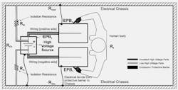
While these observations suggest multiple isolation barriers, depending on specifics of the devices and circuits, shared isolation barriers can also be employed where possible (see figure).
What’s the Purpose of Monitoring Isolation Resistance?
Isolators in circuits can help to manage the differing power and voltage levels within the vehicle to ensure both safety and performance. In addition to the physical separate of circuits and components and the role of insulation, isolators can support information (signal) and power transmission as appropriate.
Isolation matters to EV BMS, because it can reduce electrical interference and strengthen the accuracy of cell monitoring. It can also help reduce power fluctuation and protect against spurious data. In battery packs, isolation often depends on materials such as polyimide or ceramics that can prevent high voltage leakage into control circuits.
Within drivetrains, isolation is central to traction inverters, where high-voltage DC is usually converted to power AC motors. Furthermore, this system must protect control systems and guard against transients and EMI. Isolation also plays a role in delivering the precise control of power that users want and need.
A Final Safeguard: Interlock Systems
Another important role for isolation is in the high-voltage interlock systems, which are designed to make contact with high voltage in a vehicle difficult if not impossible. Often this mechanical and electrical isolation system incorporates a low-voltage “loop” that can monitor the integrity of the high-voltage circuits and provide a warning to a vehicle operator or technician if there’s a problem, such as a loose connector. This is done by maintaining a low-voltage system along the same physical path as the high voltage. If one is disconnected, so is the other.
Such systems can prevent accidents and misoperation as well as give out an alert when a high-voltage circuit is open.
All of these means of isolation need to be considered and built in as systems are designed and integrated to ensure both safety and performance.
References
About the Author


