Automotive Lighting Requires Reliable EMI Control
What you’ll learn:
- The importance of managing EMI, maintaining the reliability and performance of the vehicle's electronic systems, and adhering to stringent safety standards and regulatory requirements.
- Understanding the need for lighting drivers to power OLED and LED lighting applications in vehicles, with a particular focus on reducing EMI generation.
- How an integrated solution provides precise control over OLED and LED lighting through advanced features like regulated current sources and PWM, all while adhering to safety standards such as ASIL level B.
The advent of OLED and LED technologies marks a significant evolution in automotive lighting, offering a leap forward from traditional lighting solutions. These modern lighting technologies are rapidly being adopted due to their superior qualities, such as improved design flexibility, reduced energy consumption, and greater lifespan.
OLEDs, with their thin profiles and uniform light diffusion, and LEDs, known for their brightness and efficiency, are reshaping the visual dynamics of vehicles, contributing to a more distinctive and futuristic appearance.
However, the shift to these advanced lighting systems isn’t without its challenges. A key concern in the automotive industry is ensuring electromagnetic compatibility (EMC), which involves the seamless operation of electronic systems without interference. Electromagnetic interference (EMI) is a phenomenon where unwanted electrical noise or signals from one electronic device disrupt the normal functioning of another, potentially leading to erratic behavior or failure.
In the context of automotive lighting, EMI could interfere with critical vehicle systems such as radio communications, navigation, and safety-related electronics. This is particularly problematic in the tightly integrated environment of modern vehicles, where numerous electronic systems operate in close proximity.
Managing EMI is therefore crucial, not only for maintaining the reliability and performance of the vehicle’s electronic systems, but also for adhering to stringent safety standards and regulatory requirements.
EMC Solutions for Automotive OLED and LED Lighting Using the L99LDLH32
What’s needed is a driver to power OLED and LED lighting applications in vehicles, with a particular focus on reducing EMI generation.
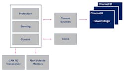
The L99LDLH32 automotive lighting driver developed by STMicroelectronics is a component designed to tackle these EMC challenges. The L99LDLH32 is an intelligent high-side driver, equipped with 32 regulated current sources. Each source can be programmed to deliver a specific current, enabling the independent and precise control of individual pixels within a lighting panel. This capability facilitates the creation of intricate lighting effects and patterns.
The driver employs an advanced high-frequency pulse-width-modulation (PWM) technique to achieve exact light-intensity control. It’s further refined by the programmed high-resolution current for each unique lighting string.
Comprehensive functions are incorporated for durable and safe operation. Advanced diagnostic and protection circuits provide functional-safety control, along with voltage and temperature monitoring features (Fig. 1).
L99LDLH32’s Features for Precise OLED and LED Control
The L99LDLH32 offers an extensive array of configuration options, allowing it to function in various modes such as standalone, fail-safe, and bus modes. The device is also designed to meet Automotive Safety Integrity Level (ASIL) level B requirements as outlined in the ISO 26262 standard, featuring critical elements like a timeout watchdog with a limp-home function to enhance safety.
Integration is a key advantage of this device, as it comes with a built-in protocol handler and transceiver for the Controller Area Network (CAN) with Flexible Data-rate (FD) and Light specification. Such integration streamlines connectivity by obviating the need for additional external components, like timing crystals.
The CAN FD Light protocol allows for data rates up to 1 Mb/s, giving designers the flexibility to design intricate light animations and achieve smooth dimming transitions. Smooth transitions during power on and off phases are crucial for reducing electrical stress on the system and improving EMI performance.
EMI Reduction Techniques in the L99LDLH32 Lighting Driver
The L99LDLH32 is designed to curtail EMI by staggering the activation of lighting channels and introducing a delay in channel activation. Such an approach can be toggled for all channels with a single bit, giving designers control over the lighting system’s performance to meet the needs of specific applications.
This strategy is effective in reducing the sudden electromagnetic energy surge that could occur from channels switching simultaneously. Thus, it lowers the likelihood of EMI with other in-vehicle electronic systems.
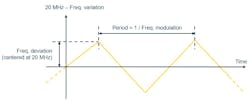
Moreover, the device integrates a clock-dithering function specifically designed to further mitigate EMI. Clock dithering within the L99LDLH32 works by modulating the frequency of the internal 20-MHz oscillator, which is responsible for timing the LED switching operations—a common source of EMI.
The modulation is achieved through the application of a triangular waveform to the oscillator. This waveform is well-suited for dithering due to its linear and predictable frequency changes, ensuring smooth transitions. With three dedicated bits, the user can set the triangular dithering waveform, defining the frequency modulation and frequency deviation relative to the 20-MHz center frequency (Fig. 2).
As the oscillator frequency is subtly shifted up and down by these increments, the noise is dispersed, and the peak amplitude of noise at any single frequency is effectively reduced. This dispersion is crucial because it dilutes the intensity of the electromagnetic emissions, lessening the potential for the driver to interfere with other electronic components within the vehicle.
System-Oriented Analysis for EMI Resilience in Automotive Lighting
EMI investigation can be performed with a pivotal test methodology that performs system-oriented measurements to evaluate the lighting driver's noise immunity within the vehicle's electrical environment, thus simulating real-world interference conditions.
This test, known as bulk current injection (BCI), is instrumental in assessing the robustness of the automotive lighting driver against electromagnetic disturbances.
The findings from these tests are crucial for identifying the EMI vulnerabilities and evaluating the efficacy of the implemented mitigation strategies. It leads to enhanced EMI resilience of automotive lighting systems and ensures the safety and reliability of modern vehicles.
Bulk Current Injection (BCI) Specifications
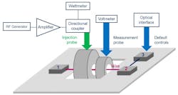
BCI characterization involves injecting disturbance signals into the wiring harness using a current injection probe to simulate the effects of EMI. The probe acts as a current transformer, with the wiring harness of the device under test (DUT) forming the secondary winding, as illustrated in the test board schematic (Fig. 3).
The objective is to replicate the impact of external electromagnetic fields on the cables without needing actual radiated fields.
The BCI test board schematic comprises:
- An RF path consisting of an RF generator, RF amplifier, dual directional coupler, wattmeter, and injection probe (toroidal antenna).
- The system under test, which includes one or more DUTs, wires for RF current injection, and a load featuring a DC power supply with line-impedance stabilization networks (LISNs) on both poles.
- Optical probes to capture signals for monitoring and, if necessary, to control the system with external signals.
BCI testing is invaluable for verifying electronic devices' immunity to EMI across a frequency range. Immunity tests vary the frequency of induced narrowband disturbances from 100 kHz to 400 MHz.
The method involves:
- Calibration: Injecting current and measuring forward and reflected power to ascertain the actual current on the DUT during testing. This step ensures accurate current levels and test setup calibration.
- Testing: Observing the DUT's response to the injected current and comparing it to specification limits. Deviations or malfunctions are analyzed to determine EMI immunity.
Automatic BCI bench calibration follows international and industry-specific standards, such as IEC 62132-3 and VW TL-81000/2018, to ensure EMC testing accuracy and reliability.
- IEC 62132-3: This IEC standard details the test methods for integrated circuits' immunity to RF interference under BCI, specifying conditions and setup, including equipment calibration.
- VW TL-81000/2018: A Volkswagen Group standard that outlines EMC testing requirements and methods, with the 2018 revision likely updating BCI testing and calibration protocols.
The calibration process plays a critical role in EMI testing because the current injected into the system isn’t measured directly. Instead, It’s deduced from the levels of RF power. This indirect measurement necessitates a precise calibration routine to ensure accurate test results.
A directional coupler is used to measure both the forward power delivered to the probe and the reverse power, effectively separating the incident and reflected power. The net power is calculated as the difference between the forward and reverse power.
During the calibration phase, the system is adapted to a 50-Ω load impedance, ensuring that the net power is effectively equivalent to the forward power. This power is then used to generate the desired current within the calibration fixture across the required frequency spectrum.
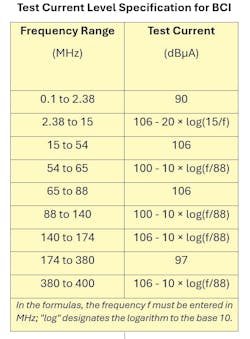
Volkswagen's technical specification, VW TL-81000/2018, details the procedures for establishing the upper limits of test current applied via BCI for frequencies up to 400 MHz. These limits are specified in the table.
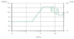
The test current as a function of frequency for the BCI test is depicted in Figure 4.
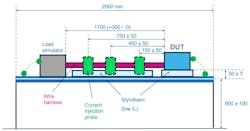
ISO11452-4 specifies two BCI testing methods: substitution (open-loop) and current-monitoring (closed-loop) methods. The test configuration for the BCI substitution method is depicted in Figure 5.
The injection probe is positioned at three different distances from the DUT: 150 mm, 450 mm, and 750 mm.
During the test performed in an anechoic chamber to avoid spreading RF power noise into the external environment, forward calibrated power is injected into the probe that’s clamped over the harness. This power is gradually increased to the level established during calibration. Since the load impedance may vary during testing, the induced current in the harness may also vary.
Conversely, the closed-loop method utilizes two probes: one for injection and another for measuring current. The calibrated power level is applied, and the harness current is measured. If the measured current falls below the specified level, the power is increased until the required current is achieved, adjusting the RF power to match the desired current reading. Depending on the impedance levels of the system under test, high RF power levels may be necessary.
Experimental Data Validating the L99LDLH32 Driver’s EMI Resilience
The test conditions for the L99LDLH32 are specified as follows:
- Battery voltage (VBAT): Set at 13 V.
- Ambient temperature (TAMB): Maintained at room temperature, 25°C.
- Load specification: A 32- × 32-pixel OLED panel is used.
- Current settings: Channels 0 to 31 are adjusted to a current of 3.8 mA.
- PWM frequency: Configured at 200 Hz.
- Dithering: Set to 100 bin corresponding to a frequency modulation of 19.5 kHz and a frequency deviation of 6.5%.
- Operating mode: The device is tested in normal mode (bus mode).
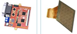
The experimental data were collected using an evaluation board that incorporates two L99LDLH32 devices to operate a 32- × 32-pixel OLED panel (Fig. 6). This evaluation board, known as the easyboard or tiny board, is designed for product assessment without the need for the significant investment of time and effort usually associated with creating a custom circuit board.
Easyboards are streamlined and practical evaluation tools connect the product directly to the load. This facilitates a direct assessment of the device and its full range of application features, which includes testing auto-protection functions in hazardous conditions.
The BCI disturbance current is introduced into four wires corresponding to the high and low input/output voltages of the CAN bus (CAN_H and CAN_L, respectively), the battery supply voltage (VBAT), and the ground connection. This setup is detailed in Figure 7.
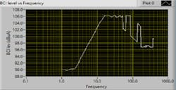
During the calibration process for the OLED driver L99LDLH32, the profile of the current that’s injected is represented graphically in Figure 8.
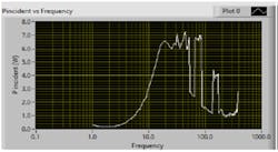
The determination of this current profile is achieved by directly measuring the net incident power (Pincident) (Fig. 9).
The criteria for identifying faults during the BCI test are determined by observing the OLED panel's response:
- In Bus Mode: For each row of the OLED panel, which consists of 32 pixels, a minimum of 31 pixels must remain lit and show no visible change in brightness when RF power is applied. The task of monitoring for any variations in light intensity falls to a human operator.
- During the Transition to Fail-Safe Mode: When the system transitions from Bus Mode to Fail-Safe Mode, the expected behavior is that 29 of the 31 lit pixels in each row will switch off, leaving only two pixels illuminated. This is in accordance with the fail-safe programming conditions.
Test outcomes demonstrate that the L99LDLH32 maintains stability, not shifting from bus mode to fail-safe mode. In addition, it exhibits no light-intensity fluctuations even when subjected to RF power levels up to 7.5 W, which corresponds to a harness current of 107 dBµA.
This robust immunity is consistently preserved across the full frequency range from 1 to 400 MHz.
Conclusion: The L99LDLH32 Lighting Driver Effectively Manages EMI
Effective EMI management is crucial for maintaining EMC in vehicle systems. An integrated solution such as the L99LDLH32 lighting driver provides precise control over OLED and LED lighting through advanced features like regulated current sources and PWM, all while adhering to safety standards such as ASIL level B. The driver integrates CAN FD Light protocol and employs EMI mitigation tactics like staggered channel activation and clock dithering to preserve the vehicle's electronic integrity.
Significantly, system-level BCI testing validates the L99LDLH32's EMI resilience, showing no variation in light intensity under high RF power conditions across a broad frequency spectrum. Such testing is crucial for confirming the driver's dependability and the overall safety of automotive lighting systems.
References
IEC 62132-3: “Integrated circuits - Measurement of electromagnetic immunity, 150 kHz to 1 GHz Part 3: Bulk current injection (BCI) method,”2007.
Volkswagen TL 81000: “Electromagnetic Compatibility of Electronic Components for Motor Vehicles - EMC changes,” Issue 2018-03.
International Standard ISO 11452-4, “Road vehicles – Component test methods for electrical disturbances from narrowband radiated electromagnetic energy, Part 4: Harness excitation methods,” Edition 5, 2020.
F. Rennig, “CAN FD light – A network protocol to control lighting,” Driving Vision News (DVN) Workshop, Munich, 27-28 Feb. 2024.
