Embarking on a New Frontier of Power Density with GaN
What you’ll learn:
- What all-electric aircraft and GaN FETs have in common.
- The differences between LLC+Buck and Boost+LLC-DCX circuits.
We’ll kick off this article with a power component recently introduced by Efficient Power Conversion (EPC): the EPC2361 enhancement-mode GaN FET at 100 V, 1 mΩ, housed in a 3- × 5-mm QFN package. This component offers a higher power density for DC-DC conversion, motor drives, fast charging, and solar maximum power point tracking (MPPT). Claimed as the lowest on-resistance GaN FET on the market, it offers twice the power density when compared to EPC’s earlier generation products.
Driven by such a FET or similar types of components, let’s look at high-power-density applications that are pushing the limits of power design.
GaN Needed for More-Electric Aircraft (MEA) and All-Electric Aircraft (AEA)
MEA and AEA are very good solutions for fuel consumption and combating greenhouse gas emissions. Thus, their applications always need high power density along with solid reliability.
Aircraft typically have a limited load. Reducing the weight by just one kilogram will have a cost savings of $4,500 for medium- and short-range aircraft during 20 years of operation. As a result, high-power-density converters become vital to these systems.
On this front, scholars at Nanyang Technological University - NTU Singapore presented their work with a weight-optimized power-supply design for aircraft.
Research focused on an optimized converter architecture that reduces weight and improves aircraft performance. It was determined that a high-voltage DC (HVDC) electric power system (EPS) with a ±270-V main DC bus would be the best future structural design for MEA and AEA. As of this point, there’s not much research on the weight optimization of the converters that connect the 3-kW HVDC 270-V bus and the 28-V DC load in the AEA and MEA.
>>Download the PDF of this article, and check out the Library Series for similar articles and videos
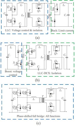
A planar transformer with inductor is used in the design, leading to the best performance in the LLC resonant converter. High reliability, coupled with a light weight, will lead to the selection of one of the three schemes shown in Figure 1.
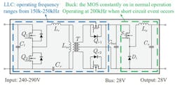
Among the three converters, the LLC+Buck, was chosen for the final scheme (Fig. 2).
The LLC+Buck circuit influences the overall weight and is the lightest of the three converters shown in Figure 1. Typically, this scheme has a tradeoff between weight, efficiency, and gain range:
- Comparing weight: The LLC+Buck is lighter than the Boost+LLC-DCX since the boost inductor must function at a high of 270 V, while the buck inductor only operates at 28 V. The larger and heavier magnetic core in the boost inductor eliminates the Boost+LLC-DCX in this case.
- Comparing efficiency: The Boost+LLC-DCX has the highest efficiency since it essentially operates for two distinct reasons. First, the LLC-DCX is able to constantly operate quite close to the resonant frequency, which is the highest efficiency point of the LLC resonant circuit. Second, the boost is situated at the high-voltage side. The conduction loss is less than a buck in the LLC+Buck design. Therefore, the phase-shifted full-bridge will have the lowest efficiency for the zero-voltage-switching (ZVS) problem when under light load condition with a large current in the filter inductor.
- Comparing the short-circuit protection reliability: The LLC+Buck, along with the phase-shifted full-bridge, will perform much better. Both of these output stages exhibit the capability of strong voltage regulation. However, the LLC circuit in the Boost+LLC-DCX design exhibits a gentle frequency-gain curve. As a result, the duty cycle needs to be changed, or it must function at a high frequency to limit the current. This doesn’t offer a very reliable means of short-circuit protection.
- Comparing complexity: With the control and hardware design complexity, the simplest option is the phase-shifted full-bridge since it has a single-stage circuit, along with phase-shift modulation. Also, the pulse-width modulation (PWM) of the Boost+LLC-DCX design is very simple. However, the voltage control strategy of the LLC+Buck design needs frequency modulation and is fairly complex.
Takeaways are that the LLC+Buck design is fairly complex, and its efficiency is lower than the Boost+LLC-DCX design, but it will function better in short-circuit protection reliability and weight. So, based on the high-reliability principle and the minimization of weight, the 3-kW LLC+Buck is the best choice.
How to Further Minimize Weight
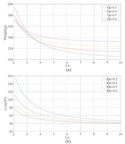
Let’s look at the LLC circuit resonance parameters that may also influence weight. In this case, there’s a tradeoff with weight, gain range, and efficiency. First, pinpoint the parameters that will minimize the LLC converter weight and control any losses within a suitable range. Then analyze the relationship between the loss of the circuit and parameters, along with the weight (Fig. 3).
Resonant parameters and weight
The resonant parameters will mostly influence the weight of the magnetic components. Thus, the designers chose a planar transformer and inductor for the LLC circuit.2 The magnetic components’ weight for the magnetic core plus the weight of the winding is included in the weight of printed-circuit-board (PCB). Reference 2 goes into great on how to estimate the weight of the magnetic core.
Resonant parameters and losses
The resonant parameters, as measured, will mostly influence the primary-side current that may impact conduction loss of the components in that primary side. It takes into account the magnetic core losses in the resonant inductor plus conduction loss in the transformer’s windings on the primary side.
Conduction losses for each component is able to be calculated via the use of the square of Ir, which will be multiplied via the equivalent series resistance value on the primary side. We can estimate the core losses of a resonant inductor with Equation 1:
where:
- ml (in g) and mt (in g) are the mass of the magnetic core of the inductor and transformer.
- Pv (in mW/cm3) is the unit volume loss, which can be acquired by the frequency and Bm from the datasheet of the core material that’s chosen.
- dc (in g/cm3) is the density of the core material chosen.
- ml (in g) is the mass of the magnetic core of the inductor.
- mt (in g) is the mass of the magnetic core of the transformer.
- C1 and C2 are constants that are determined via the core shape and material.
- Bm is equal to the variation value of the AC magnetic flux density since there’s no DC component in the resonant inductor current.
Now the LLC resonant circuit can reach ZVS when the power devices on the primary side turn on and the turn-on loss may be disregarded. Via the analysis of the working process of the LLC circuit, the power devices’ turn-off current is the Im.
Switching losses can now be estimated using Equation 2:
where:
- tcross is in seconds and is defined as the crossing time of the current and voltage wave during the power devices’ turn-off process.
- fsw is the switching frequency.
Figure 3 shows the relationship of the estimated weight of the magnetic components, the losses on the primary side, and the parameters to be designed.
Therefore, when Qe is fixed, the efficiency increases; the weight of the magnetic components will decrease as Ln rises. When Qe increases, the weight of the magnetic components will rise in regions of large Ln, and the loss will decrease.
Optimized Design Methodology
There are a few restrictions when selecting Qe and Ln. The optimized resonant must satisfy several restrictions to have the optimum design requirements:
Restriction 1
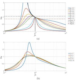
The peak gain that’s attainable in the inductive region of the LLC is higher than needed maximum gain. To reach ZVS within the entire regulation range, the resonant input impedance must be inductive within the designed operating range (Fig. 4).
The boundary of the inductive area is the solid black line phase = 0 in Figure 4a.
If we fix Qe and Ln, the critical frequency may be solved and the Mg values at these frequencies is the attainable peak gain. This boundary may be achieved by solving this equation:
where:
- Lr is the resonant inductor.
- Cr is the resonant capacitor.
Restriction 2
At the maximum frequency, Mg is smaller than the required minimum gain. To avoid any high losses, a maximum frequency must be set when the LLC circuit is designed. Selecting Ln and Qe determines the minimum Mg.
Restriction 3
Now the magnetizing current should be large enough to finish the ZVS of the primary-side power devices that are within the deadtime. A large Lm can weaken the Im—this charges the capacitor within the deadtime and reduces the voltage of the power devices to be turned on to zero while realizing the ZVS. If the Ln is too large, the power devices’ ZVS might not be able to properly achieve their function.
Restriction 4
The temperature rise of every component is within their proper limits. However, even though the overall losses are estimated, the temperature rise of each component has their separate individual limitation. Still, the losses of each component must be checked.
Higher Power Density with GaN Integration
The performance of eGaN FETs (refer to first paragraph) is expected to double every two years, resulting in increased performance from a smaller form factor. GaN devices increase the efficiency, shrink the size, and reduce system cost for 48-V power conversion.
Due to the significant improvements GaN offers in switching performance and size reduction, power-supply designers realize that GaN FETs lead to higher power density and more efficient 48-V power supplies.
For example, the EPC9143 uses the EPC2053 100-V eGaN FET to achieve 96.6% efficiency up to 25 A (300 W) in a very small 1/16th-brick form factor. This represents a power density greater than 610 W/in.3.
In high-density server applications, high power density and efficiency can be realized by using simple topologies such as a DC-DC converter with an LLC topology. eGaN FETs are well-suited for LLC converters since their combined low gate charge (QG) with 5-V gate operation yields very low gate power consumption, ultra-low on-resistance, and low output capacitance charge (QOSS)
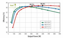
Figure 5 shows a power density of almost 1,700 W/in.3 (104 W/cm3), which is achieved with an overall efficiency more than 98% using a GaN-based LLC solution.
Simplified, High-Efficiency Power-Conversion Design
When delivering efficient power conversion, especially in high-voltage systems, GaN power density simplifies power designs. Its impact can be felt in applications ranging from energy storage systems, electric vehicle (EV) onboard and offboard chargers, and residential AC distribution power systems to telecommunication and server power systems and DC microgrids in renewable-energy systems.
References
1. “Key Parameters and Driving Requirements of GaN FETs,” Hagar Mohamed, Donaldo Sanchez, Application Brief SLUAAM0 – August 2022, Texas Instruments.
2. “Design and weight optimization of a high-power-density DC power supply for aircraft,” Daoxin Tong, Xu Yang, Zheyuan Yu, Kangping Wang, Yuxuan Chen, College of Electrical Engineering, Xi’an Jiaotong, Xi’an, China, 2021 IEEE 12th Energy Conversion Congress & Exposition – Asia (ECCE-Asia), 2021.
3. “GaN – the New Frontier for Power Conversion,” Alex Lidow PhD, Efficient Power Conversion (EPC), Bodo’s Power Systems.
4. “GaN Integration for Higher DC-DC Efficiency and Power Density,” Alex Lidow, David Reusch, and Johan Strydom, Efficient Power Conversion.
5. “Rethink Power Density with GaN,” Masoud Beheshti, Electronic Design.
>>Download the PDF of this article, and check out the Library Series for similar articles and videos
About the Author

Steve Taranovich
Freelance Technical Writer, Phoenix Information Communication LLC
Steve is a contributing editor to Electronic Design.
Author of the non-fiction “Guardians of the Right Stuff,” a true story of the Apollo program as told by NASA and Grumman Corp. engineers, an astronaut, and technicians.
Experienced Editor-In-Chief of EETimes/Planet Analog and Senior Technical Editor at EDN running the Analog and Power Management Design Centers from 2012 to 2019.
A demonstrated history in electronic circuit design and applications for 40 years, and nine years of technical writing and editing in industry. Skilled in Analog Electronics, Space-related Electronics, Audio, RF & Communications, Power Management, Electrical Engineering, and Integrated Circuits (IC).
1972 to 1988 worked as a circuit design engineer in audio (8 years) and microwave (8 years). Then was Corporate Account Manager/applications engineer for Burr-Brown from 1988 to 2000 when TI purchased Burr-Brown. Worked for TI from 2000 to 2011.
Strong media and communication professional with a BEEE from NYU Engineering in 1972 and an MSEE from Polytechnic University in 1989. Senior Lifetime member of IEEE. Former IEEE Long Island, NY Director of Educational Activities. Eta Kappa Nu EE honor society member since 1970.
