User-Configurable Multiphase Converters Can Handle Up to 450A Loads
Designers are confronted with the task of supplying power to a wide range of devices that include ASICs, processors, memories, and FPGAs employed in data centers and telecom systems. Responding to the need for this powering flexibility are configurable digital multiphase PWM controllers with associated external Smart Power Stages that combine to support loads from 10A to 450A.
Intersil Corporation’s digital multiphase PWM controllers and their associated Smart Power Stages provide a scalable output of 10A to 450A. These digital PWM controllers include PMBus v1.3 and Adaptive Voltage Scaling Bus (AVSBus) that supports dynamic power minimization.
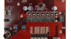
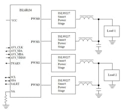
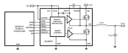
One of these digital multiphase controllers is the ISL68134, which can be programmed as a single output X+Y=<4, for instance as a 4+0, dual output 3+1 or 2+2 phase operation. Operation using less than four phases between two outputs is also supported. In a typical application, PWM outputs drive the ISL99227 Smart Power Stage in a multiphase configuration. Fig. 1 is a simplified diagram of the ISL68134 showing its four outputs configured as 2+2.
When communicating with multiple PMBus devices on a single bus, each device must have its own unique address so the host can distinguish between the devices. The device address can be set using a 1% resistor on the SA pin according to the pin-strap options.
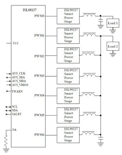
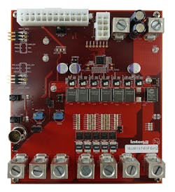
Although the ISL68137 supports arbitrary phase assignment, it is good practice to assign phases to Output 1 in descending sequential numerical order starting from Phase 6. For example, a 4-phase rail could consist of phases 6, 5, 4, and 3. For Output 0, phases would be assigned starting from Phase 0 in ascending sequential numerical order.
To produce optimal efficiency across a wide range of output loading, the ISL68134 and ISL68137 support optional automatic phase dropping. Enabling automatic phase dropping causes the number of active phases at any time to be determined solely by load current. By shedding phases when the load is idling, the system can save power by not switching unnecessary power stages. Adjustment on where phases are added and dropped can be controlled precisely by the user.
Both the ISL68134 and ISL68137 employ a proprietary linear synthetic current modulation scheme that improves transient performance. It is a unique constant frequency, dual edge PWM modulation scheme with both PWM leading and trailing edges being independently moved to give the best response to transient loads. Current balance is an inherent part of the regulation scheme. The modulation scheme is capable of overlapping pulses should the load profile demand such operation, allowing fast transient response and saving output capacitance. In addition, the modulator is capable of adding or removing pulses from a given cycle in response to regulation demands while still managing a constant frequency.
Enhancement Features
ISL68134 and ISL68137 features include:
- AVSBus control
- Diode braking for overshoot reduction
- Current sense support
- Load line regulation
- Multiple temperature sensing options
- User-configurable switching frequency from 200 kHz to 1 MHz
- Current balancing across all frequencies and slew rates
These ICs feature on-chip nonvolatile memory (NVM) to store up to eight unique configurations, allowing the user to select via pin-strap—giving system designers increased power density to configure and deploy multiple configurations.
Use of the AVSBus in both controllers complements the PMBus by providing a common interface that accelerates point-to-point communication between the controller and the load to statically and dynamically control processor voltage, thus delivering a balanced and power efficient solution. AVSBus can be used exclusively once the device is configured via PMBus.
The AVSBus is a 50-MHz bus that connects directly to a processor to communicate telemetry data and deliver efficiency savings through adaptive voltage positioning. The ISL68134 and ISL68137 controllers and ISL99227 60A smart power stage support CPU core voltages, memory, and auxiliary power rails. This enables designers to customize their solution to meet any rail requirements.
Adaptive Voltage Scaling (AVS) is a closed-loop dynamic power minimization technique that reduces power based on the ICs actual operating conditions. Typically, most ICs operate so that they meet their most demanding application throughput requirements under worst-case operating conditions. This can waste power because most ICs do not always operate under typical operating conditions. AVS continually adjusts IC operating voltage, which minimizes power consumption.
ISL68134 and ISL68137 provide comprehensive fault management:
- Pulse-by-pulse phase current limiting
- Total output current protection
- Output and input OV/UV
- Open voltage sense detect
- Black box recording capability for faults
- Active temperature monitoring
Fault monitors trigger configurable protective measures to prevent damage to a load. In addition, Power-Good indicators (PG0/PG1) can link to external system monitors. Faults may be enabled or disabled individually. Each fault type can also be configured to either latch off or retry indefinitely.
Doubling Phases
Intersil’s proprietary ISL6617A can double the number of phases that a 3.3V multiphase controller can support. For example, it can convert the 7-phase ISL68137 to 14 phases while balancing current in each pair. It minimizes the number of analog signals that interface between the controller and drivers in high phase count scalable applications. It does not require the common COMP signal, usually used in conventional cascaded configurations, which improves noise immunity and simplifies the layout. Furthermore, the ISL6617A provides a low parts count and low cost advantage over conventional cascaded techniques.
The ISL6617A also features tri-state input and outputs that recognize a high-impedance state, working together with Intersil multiphase PWM controllers and power stages to prevent negative transients on the controlled output voltage when suspending operation. This feature eliminates the need for the Schottky diode utilized in a power system to protect the load from excessive negative output voltage damage.
To facilitate configuration development for the ISL68134 and ISL68137, the PowerNavigator GUI provides a step-by-step arrangement for setup and parametric adjustment. This software allows simple configuration and monitoring of multiple digital-DC devices using a PC with a USB interface. Combined with the drag-and-drop GUI interface, it simplifies configuration and changes parameters, telemetry, or rail sequencing of a digital power supply design. PowerNavigator software supports Intersil’s portfolio of PMBus-enabled digital power products, including digital regulators, controllers, multiphase devices, power modules, and digital power monitors.
Once a configuration has been set, the user may employ PowerNavigator to monitor telemetry or use a direct PMBus interface based on the supported command set. Thresholds for automatic phase add/drop are user-programmable using the PowerNavigator GUI.
Smart Power Stage
The ISL99227 and ISL99227B are optimized drivers and power stage solutions for high density synchronous DC/DC power conversion. The ISL99227 is intended for 3.3V PWM logic and the ISL99227B is for 5V PWM logic. They include high performance drivers, an n-channel MOSFET functioning as a bootstrap diode, and a MOSFET pair optimized for high switching frequency buck voltage regulators. This circuit is actually an enhanced version of the familiar DrMOS module. Figure 4 shows the smart power stage circuit and interface.
ISL99227 60A Smart Power Stage Features
- 4.5V to 18V input range
- 60A current capability with 25V rated synchronous MOSFETs
- 200 kHz to 2 MHz operation
- Integrated current sensing, 3% accuracy across line, load and temperature
- Differential current reporting at 5mV/A eliminating DCR error and noise
- 3.3V compatible tri-state PWM input
- Integrated temperature sensing with fault monitoring
- Accurate current outputs
- Thermal reporting outputs
- High MOSFET overcurrent protection
- High MOSFET short circuit protection
- Over-temperature protection
- VCC undervoltage lockout (UVLO)
- VIN UVLO
The ISL99227 and ISL99227B use dead time control optimized for high efficiency and prevents simultaneous conduction of both MOSFETs. Should the driver have no bias voltage applied and be unable to actively hold the MOSFETs off, an integrated 20kΩ resistor from the upper MOSFET gate-to-source will aid in keeping the upper MOSFET device in its off state. This can be especially critical in applications where the input voltage rises prior to the ISL99227, ISL99227B supplies.
The ISL99227 supports a 3.3V PWM tri-level input and is compatible with the digital multiphase controllers. Should the device remain in the tri-state window for a set hold-off time, the driver will force both MOSFETs to their off states. When the PWM signal moves outside the shutdown window, the driver immediately resumes driving the MOSFETs according to the PWM commands. This feature is utilized by the PWM controllers as a method of forcing both MOSFETs off. Should the PWM input be left floating, the pin will be pulled into the tri-state window internally and thus force both MOSFETs to a safe off state.
Lower MOSFET current is monitored and a signal proportional to that current is the output on the IMON pin (relative to the REFIN pin). The IMON and REFIN pins are connected to the current sense inputs on the multiphase controller. This method eliminates the need for external RSENSE or DCR sensing of the inductor current while providing an accurate, temperature-compensated current signal.
The ISL9927/B employs a 5×5 mm PQFN package for its multi-chip module. The PQFN has superior thermal performance with 20-mil-thick copper leadframe and solder die-attach. The small footprint provides a cost-effective and area-efficient solution for multi-chip power IC products.
Digital Family Members
The ISL68137 and ISL68134 are just the first members of Intersil’s digital controller family. There are other controllers that utilize the AVSBus to power and communicate with ARM-based processors in network routers, switches, servers, storage, and wireless telecom equipment. Two general-purpose controllers (ISL68127 and ISL68124) are intended for power network processors, FPGAs, SoCs, and graphics accelerators. Plus, eight controllers (ISL69147/44, ISL69137/34, ISL69128/27, and ISL69125/24) add a secondary high-speed interface (SVID or SVI2) to power the latest Intel and AMD processors in cloud computing applications that make up the Internet of Things (IoT) backbone.
