Dostal's Designs: Selecting the Right Inductor Current Ripple
This video/article is part of Dostal's Designs series in Ideas for Design and the TechXchange: Power Supply Design. You can also post a question.
Members can download this article in PDF format.
A switching regulator converts an input voltage to a higher or lower output voltage. For this, an inductor is used to store energy temporarily. The size of this inductor depends on the switching frequency of the switching regulator as well as the expected current flow through the circuit. How exactly is the correct inductance value selected? It can be done using a commonly used formula that contains the inductor current ripple.
In the datasheets for most switching regulators and in most application notes and other explanatory texts, an inductor current ripple of 30% during nominal load operation is given as a recommendation. This means that at the nominal load current, the inductor current peaks lie 15% above the average current and the inductor current valleys lie 15% below the average current. Why is this inductor current ripple, or current ripple ratio (CR), of 30% usually selected as a good compromise?
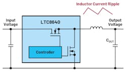
For a buck converter such as the one shown in Figure 1, Equation 1 applies:
This equation calculates the required inductor value L for a buck converter based on the CR. This ratio is usually specified as 0.3, or 30%, peak-to-peak ripple. Here, D is the duty cycle and T is the cycle time, which depends on the respective switching frequency.
What Happens with Different Inductor Current Ripples?
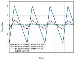
Figure 2 shows the inductor current ripple (CR) of 30% in a circuit with an output current of 3 A (in red). This is the compromise that is usually selected in switching-regulator circuit designs. The waveform shown in blue has an inductor current ripple of 133%, and the waveform shown in green has an inductor current ripple of 7%.
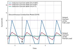
Figure 3 illustrates what happens when the same circuit is operated with part of the nominal load as the output current, such as 1 A. At a high inductor current ripple, shown by the blue line in Figure 3, the energy in the inductor is completely discharged in every cycle. This mode is called discontinuous conduction mode (DCM). In this mode, the control-loop stability behavior changes and a higher output voltage ripple can occur.
A certain ripple current ratio is needed to avoid DCM. With a ripple current ratio of 30%, a good compromise is achieved. If the ripple current ratio is low, even at partial loads, the system is mainly operating in continuous-current conduction mode. The circuit can thus be optimized for operation in this mode.
What if the Selected Ripple Current Ratio Is Too High?
At high ripple current ratios of greater than 30%, the inductor is smaller and thus cheaper. Unfortunately, the peak currents increase dramatically and generate more electromagnetic interference (EMI) than is absolutely necessary in a typical circuit. In addition, continuous conduction mode (CCM) can only be reached at higher load currents. This doesn’t have to be a problem, but the operating behavior in this mode is changed and must be considered in the circuit design.
In addition, output-voltage ripple is higher than for a lower inductor current ripple.
What are the Effects of Selecting a Ripple Current Ratio That's Too Low?
For low ripple current ratios of less than 30%, the inductor is large and accordingly expensive. The load transient response is also slower due to the large size of the energy-storage device.
If, for example, a high load current is disconnected rapidly, the energy stored in the inductor has to go somewhere. This increases the voltage across the output capacitor (COUT). The more energy in the inductor, the higher the output voltage excess. This excess voltage can damage the supplied circuit.
If the advantages and disadvantages of different inductor current ripple ratios are weighed, then values of around 30% seem to represent a good tradeoff for most applications. However, deviations are permissible in some cases as long as the resulting effects are acceptable.
Read and view more videos/articles in the Dostal's Designs series in Ideas for Design and the TechXchange: Power Supply Design. You can also post a question.


