Electromagnetic Compatibility of Switching Power Supplies: Part 1: Definitions, Standards, International Regulations and Compliance
”Switching power supply” is a generic term that describes a power source with a circuit to convert dc to ac voltages that can be further processed into another dc voltage. Switching power supply can be categorized as ac-dc power supplies (ac input) or dc-dc converters (dc input) since both incorporate dc to ac conversion for voltage change. By virtue of their inherent design characteristics, switching power supplies generate electromagnetic interference composed of signals of multiple frequencies. The dc-dc converter converts the input dc voltage to an ac voltage that can be stepped up or down via a transformer. Ac-dc power supplies also utilize high frequency circuits for voltage conversion. However, the internal ac voltage in either case is not a pure sine wave but frequently a square wave that can be represented by a Fourier series that consists of the algebraic sum of many sine waves with harmonically related frequencies.
These multiple-frequency signals are the source of conducted and radiated emissions which can cause interference to both the equipment in which the power supply is installed and to nearby equipment which may be susceptible to these frequencies.
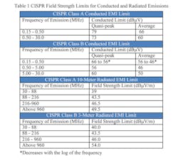
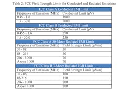
Switching power supplies generate EMI, which is subject to FCC and CISPR regulations (see below). Since Class A electronic equipment is marketed for use in a commercial, industrial, or business environment, and Class B electronic equipment is marketed for use in a residential environment, emission limits for Class B equipment, which is likely to be located in close proximity to radio and television receivers, are therefore more restrictive than Class A. In general Class B limits are more restrictive than Class A by a factor of 3 (~10 dB).
These limits apply to both systems within which switching power supplies are installed and in stand-alone applications.
Laws, Regulation, and International Cooperation
The electro-magnetic spectrum has been widely used for broadcasting, telecom and data communications through intentional emissions of electro-magnetic fields. In order to protect the electromagnetic spectrum and ensure compatibility of collocated electrical and electronic systems, regulatory bodies have established standards to control conducted and radiated EMI in electronic equipment.
In the US, the regulatory body, the FCC, decrees in Part 15 that any spurious signal greater than 10 KHz is regulated and the frequency bands of these spurious emissions must be controlled according to the type of emission.
Signals radiated and coupled through the air known as radiated emissions, must be controlled between 30 MHz and 1 GHz. Conducted emissions, i.e., those RF signals contained within the ac power bus, must be controlled in the frequency band between 0.45 MHz and 30 MHz.
The FCC further categorizes digital electronic equipment into Class A (designated for commercial, industrial, or business environments) and Class B (designated for use in a residential environment). Emission standards are more restrictive for Class B devices since they are more likely to be located close to other electronic devices used in the home.
In Europe, one of the main standards is CISPR 22, adopted by the majority of the European Community. CISPR 22 also differentiates between Class A and Class B devices and establishes conducted and radiated emissions for each class. In addition, CISPR 22 requires certification over a wider frequency range of 0.15 MHz to 30 MHz for conducted emissions.
In reality, the FCC and CISPR 22 regulations have been harmonized and either standard, with minor exceptions, can be used to certify digital electronic equipment. Harmonization requires that the same standard be used for both conducted and radiated emissions. Measurements made above 1 GHz must be made in accordance with FCC rules and limits as CISPR 22 has no specified limits for frequencies above 1 GHz and conducted / radiated emission limits specified in FCC Part 15 and CISPR 22 are within a few dB of each other over the prescribed frequencies. However, FCC limits are given in μV and CISPR limits are given in dBμV, so conversion of the units for one set of limits is necessary for direct comparison
Emissions
EMC Testing and Compliance
EMC testing and compliance is performed according to the test procedure defined in ANSI C63.4-2009 “Methods of Measurement of Radio-Noise Emissions from Low-Voltage Electrical and Electronic Equipment in the Range of 9 kHz to 40 GHz”. This ANSI Standard does not include either generic or specific product related limits on conducted and radiated emissions.
These limits are specified in the FCC and CISPR documents discussed above. It is worth noting that testing is done with the entire system, not just the power module. Even external power supplies that are in compliance with the regulations as a standalone product need to be tested with the end-system.
EMI/EMC Fundamentals Sources and Associated Frequencies
EMI can first be categorized as transient or continuous interference. Transient EMI arises when the source emits a short duration pulse of energy rather than a continuous signal. Sources include switching electrical circuitry, as well as electrostatic discharge (ESD), lightning, nuclear and nonnuclear electromagnetic pulse weapons, and power line surges. Repetitive transient EMI can be caused by electric motors, gasoline engine ignition systems and continuous digital circuit switching.
Continuous interference can be further subdivided by frequency band. Frequencies from a few tens of Hz up to 20 KHz are classified as audio - power supply hum and associated wiring, transmission lines and substations, audio processing equipment and demodulation of high frequency carrier waves such as those seen in FM radio transmission…
Radio frequency interference (RFI) occurs in a frequency band from 20 kHz and above (the level is increasing as new technologies emerge). These include wireless and radio frequency transmissions, television and radio receivers, industrial, scientific and medical equipment, and high frequency circuit signals such as those in microprocessors, microcontrollers, and other high speed digital equipment.
EMI Coupling
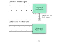
Coupling occurs either via conduction, radiation or induction. Conducted EMI emissions are measured up to 30 MHz. Currents at frequencies below 5 MHz are mostly differential mode, while those above 5 MHz are usually common mode (Fig. 1).
The differential mode current is the expected current on a two wire pair, i.e., current leaves at the source end of the line and comes back on the return side of the line. The noise is measured on each line with respect to a designated reference point. Differential mode currents flow between the switching supply and its source or load via the power leads and these currents are independent of ground. Consequently no differential mode current flows through ground.
Common mode currents flow in the same direction in or out of the switching supply via the power leads and return to their source through ground. In many cases, common mode noise is conducted through parasitic capacitance in the circuit but can also flow through the capacitance between the case and ground.
Radiated coupling occurs when source and receptor (victim) act as radio antennas. The source radiates an electromagnetic wave that propagates across the open space between the source and the victim and is received by the victim.
Inductive coupling (either electrical or magnetic) is rare relative to conductive or radiated coupling and occurswhere a short distance separates source and receptor.
Electrical induction occurs when a varying electric field exists between two adjacent conductors and causes a change in voltage across the gap. Whereas magnetic induction occurs when a varying magnetic field exists between two parallel conductors, inducing a change in voltage along the receiving conductor.
Characterization of the EMI problem requires understanding of the interference source and signal, the coupling path to the victim and the nature of the victim, both electrically and in terms of the significance of the malfunction. The risk posed by the threat is usually statistical in nature; so much of the work in threat characterization and standards setting is based on reducing the probability of disruptive EMI to an acceptable level rather than its assured elimination.
Summary
Power modules are one of many components within a system and EMI requirements, both radiated and conductive, apply to an overall electronic system. Since the EMI requirements apply to the overall system, significant effort must be expended on system design to limit noise.
An understanding of EMI fundamentals and best practices to mitigate the different types of EMI when implementing a power supply is crucial in design. However, it is also important to understand that a power supply is just one part of an electronic system with multiple EMI sources, so evaluating the power supply’s EMI performance within a system is vitally important.


