About the time APEC rolls around in March 2014 there should be a new PMBus Version: 1.3. This will be the fourth version of PMBus that started as Version 1.0. Its evolution started in 2004, Artesyn Technologies (now part of Emerson Electric) proposed the PMBus initiative. Early the following year, it was formalized as a special interest group (SIG) and opened to global membership. PMBus Adopters and Members enjoy early access and the ability to influence the specifications. The protocol is now in the public domain, and the SIG, known as the System Management Interface Forum, is responsible for further developing and promoting the standard.
PMBus 1.2 had become the standard for intelligent power management. As is usually the case, with continued use there was a trend to improve on the Standard. Among the projected changes for the improved Version 1.3 are the following core enhancements:
· 1 MHz Bus Speed, 2.5X Faster Throughput
· Floating Point Data Format
· IEEE 754 Industry Standard
· Half Precision
· 16-Bit Number
· NaN and ±Inf
· Easy Conversion to C Types
· Global Process Call
· Extension of SMBus ARA specification
· Enables intelligent global queries
· Application Support
· Device Discovery
· Prioritized Fault Management
· Faster Bulk Reads
· Relative Output Voltage Thresholds
· Margin Levels
· Warn Limits
· Fault Limits
· Power Good Limits
· Mandatory Clock Stretching Support
· Backwards Compatible to Previous Versions
· Same Open Drain Signaling
· Uniform Number System
· Negative Numbers
· NaN and ±Inf
· Easy Conversion to C Types
· Values Specified as a % of Output Voltage
· Changing VOUT_COMMAND Moves All Thresholds
The major new addition to PMBus is the AVSBus that is an interface designed to facilitate and expedite communication between an ASIC, FPGA or processor and a POL control device on a system, for the purpose of adaptive voltage scaling. When integrated with PMBus, AVSBus is available for allowing independent control and monitoring of multiple rails within one slave.
The AVSBus is behaviorally and electrically similar to SPI bus without chip select lines. AVS_MData and AVS_SData are equivalent to MOSI and MISO. AVS_Clock is equivalent to CLK of the SPI bus. Maximum bus speed is 50 MHz. AVSBus functions include:
• Asynchronous feedback from the slave by pulling low on the AVS_SData line during idle mode indicating VGood OR an Alert has been generate.
• Every frame start by the master generates a status response from the slave
• Every ACK by a slave is followed by a status response from the slave
Status response
• VGood – VOUT has reached the target voltage
• Alert – One of the bits in the AVSBus Status has been set
AVSBus Commands
• Target Rail Voltage
• Target Rail Vout Transition Rate (Rising and Falling)
• Rail Current (read only)
• Rail Temperature (read only)
• Reset Rail Voltage to Default Value (write only)
• Power Mode (Full Power, Maximum Efficiency)
• AVSBus Status (VGood, OCW, UVW, OTW, OPW)
• AVSBus Version
• Feedback from the Slave to the Master
PMBus plus AVSBus integration
• AVSBus is an application specific protocol to allow a powered device such as an ASIC, FPGA or Processor to control its own voltage for power savings
• PMBus is an open standard protocol that defines a means of communicating with power conversion and other devices allowing effective configuration and control as well as telemetry data.
• The combination of these protocols in a slave device is an efficient and effective solution for systems containing loads that need to adapt the operating voltage.
PMBus Revolutionized Power Converter Design
The PMBus allows power converters to be configured, monitored and maintained according to a standard set of commands. Using PMBus commands, a designer can set a power supply’s operating parameters, monitor its operation and perform corrective measures in response to faults or operational warnings. The ability to set a power supply’s output voltage allows the same hardware to provide different output voltages by merely re-programming. The ability to monitor and maintain a PMBus system enhances its reliability and availability.
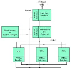
Implementation of the PMBus specification requires the design of power supplies and their associated ICs to adhere to the required interface and commands. As shown in the distributed power architecture of Fig. 1, the SMBus provides serial communication between the host computer or system manager and the PMBus compliant devices. A variation of the widely-used I2C bus, the industry-standard SMBus is a two-wire bus modified several years ago for Smart Battery applications.
When implemented, the PMBus protocol allows multi-sourced power management products. In addition, OEMs will be able to control compliant power converters using a standard set of commands. First hardware that complies with PMBus was available in 2005. This includes ICs and POL (point-of-load) converters.
PMBus Version 1.3 will enhance digital control of power converters. No longer will power converters employ mostly analog technology. The forthcoming Version 1.3 will provide a tighter “marriage” between the analog and digital worlds. Stay tuned for the formal introduction of Version 1.3 in March 2014.


