Topology and Components Selection For Cost and Performance In Automotive Converters
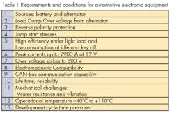
The requirements for the automotive industry are specific and are different from industrial and commercial applications. They are much closer to military requirements but the cost must be significantly lower. Some of these requirements and conditions are common with general requirements for power supplies: some are exclusive to the automotive industry, such as reverse polarity protection, load dump over voltage from alternator, peak current up to 2900 A, water resistance, and vibration. Table 1 lists the main requirement and conditions of electronic equipment for the automotive industry.
Related Articles
- Autonomous Valet Parking and Charging Of EVs Proposed For Public Transit
- Volvo Car Group Embeds Batteries, Supercaps in Carbon Fiber Body
- Is the Road of Tomorrow Electric?
- Gallery: Electric Cars from the 2014 Detroit Auto Show
- Networked Automotive Subsystems Becoming the Rule of the Road
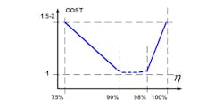
Before we start to discuss real topologies, let’s see a general relationship between cost and efficiency for power converters (Fig. 1). According to this curve, we need to stay in the minimum cost area. When we go too close to100% efficiency, cost will be extremely high. The cost effective design needs to stay between 90 to 98%, but at the same time we need to remember that efficiency itself is not the target, rather the low cost and superior performance is the target. This level efficiency can be provided only by SMPS. The switch itself can be hard switching or soft switching. Hard-switching itself is simple but it has a major disadvantage: high stress on the semiconductor at the time of switching. That requires the use of more powerful semiconductors in order to stay in the SOA. Hard switching has a collateral effect of high level of EMI. Soft switching is more complicated but it has very small switching losses and significant reduction in the level of EMI. Also soft-switching helps packaging of control together with power stage, by significantly reducing interference. Finally: General design which uses soft-switch technology will have a cost reduction compared to hard-switch technology. That’s why we use soft-switch technology.
Alternator and Inverter
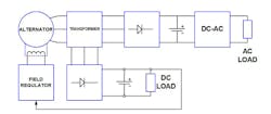
One characteristic of the automotive industry is that the alternator of a vehicle is the source of energy. This source has a slow response time that creates many problems when we use an alternator as a source for the dynamic inverter. Fig. 2 shows a block diagram of a dynamic inverter. This inverter needs to provide power for many kinds of load, preferably with fast response time. Vanner Inc. manufactures two dynamic inverters based on the same topology: an old traditional design and a modification of that, which is relatively new. Fig. 3 is a simplified regulator for a traditional inverter.
The traditional design has a 6 kW inverter and a large alternator. The modified design has a 3 kW inverter and a small alternator, but can provide start and running for a more powerful load and it costs less than the traditional one. The cost of the modified inverter is 17% lower relative to the cost of the traditional inverter. We use a different topology in modified inverter for alternator field excitations than in the traditional design.
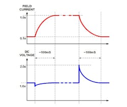
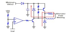
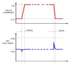
In this case, a response time is up to 100mS and there is a big voltage overshoot (Fig. 4) when heavy load is disconnected. This is because the current in the rotor is circulated with a slow decay and the alternator still produces energy while the current decays. Fig. 5 shows simplified new topology for a field regulator of alternator [1]. With this topology, we have a faster response time and a significant reduction in overshoot voltage on the DC link that reduces stress for other components (Fig. 6). In this case, the rotor current decays much faster as energy from rotor is returned to the source. Also when heavy load is connected, the current in the rotor rises faster because the voltage of the source for the rotor is at least twice higher than a conventional regulator. In other words, this increases the reliability of the whole system of the vehicle. Finally we have reduced electrical stress, improved response. DC-AC inverter of the modified design has ZCS turn-on technology. This way, efficiency improves and there is a cost reduction of the package and EMI filter. The overall result is a reduced cost for the customer.
DC-AC Inverter
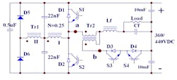
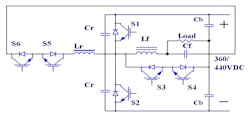
New DC-AC (Fig. 7) inverter has complete soft-switch technology and higher efficiency, around 97% with commutation frequency of 40kHz [2,3]. Soft-switch technology helps us to reach higher commutation frequency, which reduces the size of the filter, and finally we get a cost reduction. Now the next question: which soft-switch technology can we use in this case? Let’s see a comparison between our new DC-AC inverter and DC-AC inverter with an auxiliary resonant commutated pole (Fig. 8). We decided to make this comparison because both inverters have the same main electrical performance: efficiency, electromagnetic emissions, and commutation frequency. But the inverter with an auxiliary resonant commutated pole has a higher cost around 2-3%, and reduced reliability. This is because the inverter with an auxiliary resonant commutated pole has additional active switches, which require more complicated control and additional gate drivers. Designs with the auxiliary resonant commutated pole were developed for inverters, which use SCRs. At the present time for this purpose they use IGBT.
That’s why a design engineer needs to have a good justification to use an auxiliary resonant commutated pole. The new components require the use of new techniques and this is important for the automotive industry where a long product lifetime is expected and obsolescence will create problems. One more point is about a DC-AC converter, which is used for motor drive in hybrid and electrical vehicles. When DC-AC converter is used without a filter, cables which provide connections between a converter and motor can be sources of EMI. Longer cable will have higher level of EMI. For EMI reduction, we need to use a special shielding of cables. Cost of this shielding can reach 30% of the converter price. Cost of filters can be up to 10% of the converter price. All this shows how we need carefully to choose a configuration of the power stage and particularly in this case pay attention that the converter itself cannot be alone. The converter and motor should be looked at as one integrated power stage. We need to see the whole picture from the start to the end. Only this way can we get a good cost with optimal performance.
DC-DC Converter
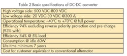
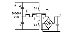
Now let’s speak about an isolated DC-DC converter which is more popular now on hybrid vehicles. Table 2 shows the basic specifications of a new bi-directional DC-DC converter. While developing this converter, we decided to reduce efficiency by 2%. This reduction helped us to reduce cost by 15%. This was done by changing components and packaging. In this converter, we use our proprietary topology Fig. 9[4,5,6,7,,9].
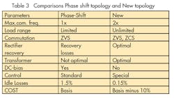
We made a comparison between our topology and phase-shift topology (Table 3). We made this comparison assuming that all topologies have the same efficiency, output power 4 kW and input and output voltage, with output current above 100A. The main advantages, which help us achieve cost reduction, are the following: the power transformer works in optimal conditions, approximately a trapezoidal waveform with roughly constant RMS voltage regardless of the input voltage. The current carried by the winding is almost sinusoidal with a duty cycle of 90% and does not change with the input voltage. This is an advantage when considering transformer losses, and along with the fact that the new topology can reach higher commutation frequency, significantly helps to reduce the size of the transformer, decreases price, and increases the transformer’s efficiency. The rectifier works with ZCS commutation and without an inductor and with a duty cycle of 90%. When we have an output current of 100 A and more, the output rectifier with an inductive filter is not a good solution, because the inductor itself is not cheap.
There will be hard switching of rectifier diodes, which will increase energy losses and EMI, and, as a result, increase cost. In this case resonant topologies with ZCS are preferable. The next very important point is what power magnetic components we need to use. During the last 15 years, we can see how the cost of power semiconductors went down and the cost of copper went up. This trend will continue. Therefore any topologies which use the transformer inefficiently (like push-pull) or with two or more power transformers, will not be considered, (although they could be viable if there are special requirements such as a space application, etcetera.) This is the first point: to use a topology where the transformer works under optimal conditions.
For our converter, we developed a power transformer, which is a physical part of the power stage, which also uses SMA with a maximum constant current of 300 ADC [8]. Full integration of a power transformer into the power stage has very strong benefits when we have a current of 100A and more. We made a comparison of our transformer with a planar transformer with the same conditions (110 kHz, 280 A output). The planar transformer has a price, which is 20% higher than our transformer and 2% lower efficiency. Efficiency is reduced because the planar transformer has not enough contact area for 280 A. If the contact area is increased, the cost will increase too. This is a second point: the transformer itself cannot be useful alone. It can be used only as part of the whole power stage. That’s why when you make a package design you need to see the whole picture.
Semiconductors
At the heart of a power converter are the power semiconductors. Clearly, the main types of power semiconductors used in the automotive industry are MOSFETs, IGBTs and bipolar transistors. For automotive applications, it is preferable to use semiconductors with a gate threshold voltage of 2-4 V or higher. With a lower gate threshold, semiconductor reliability will be reduced or the cost of the gate drive will increase significantly. That is why we do not consider semiconductors with logic level threshold or GaN type devices. GaN has the additional penalty of high cost. This raises the question: what semiconductor can we use and how can we use them? For low voltage, below 200 V, obviously a MOSFET is straightforward to use. For high voltage we have a choice: MOSFETs, IGBTs, Bipolar transistors, or a combination thereof. In this case there are many options, but we would like to examine one option and make a comparison.
For high voltage (1200 V or higher) and high current, it is very reasonable to use an Emitter Switched Bipolar Transistor (ESBT) (see Fig. 10) [10,11,12]. This configuration has many advantages: it has very low conduction and switching losses, it is useful for high commutation frequency (up to 150kHz) and has a very reasonable cost. A disadvantage is that it is not simple to drive. Let us make a comparison of an ESBT and SiC transistor. A SiC Half-Bridge module (CAS100H12AM1) costs $360. A Half-Bridge using an ESBT (STE70IE120) has similar specifications to the CAS100H12AM1 but costs $120 (cost includes four transistors, two anti-parallel diodes and two current transformers).
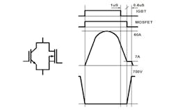
Unfortunately, the STE70IE120 is obsolete. ST has explained that there was a very low demand from design engineers. Let us look at the application of other semiconductors in this resonant topology. Fig. 11 shows this topology. We are going to make analyses when the topology operates under the following conditions: commutation frequency – 80 kHz, current via primary winding of transformer is sinusoidal with peak 60 A and duty cycle 90-95%. The switch interrupts a relatively low current around 7 A. An IGBT is unacceptable for use here because of the IGBT current tail and high commutation frequency in this application. We may use a MOSFET or combination of IGBT and MOSFET connected in parallel. The MOSFET will be turned-off around 1 µS after the IGBT. In this connection conductive losses are determined by the IGBT and switching losses also mostly set by the IGBT but are several times smaller than we would have without the MOSFET (Fig. 12). Table 4 compares different combinations of IGBT and MOSFETs. We can see that an IGBT with MOSFET has the same losses as three MOSFETS but the cost is twice smaller. We show here two ways how a design engineer may use cost effective semiconductors and not raise hopes that there might be a magic semiconductor.
EMI And Reliability
During the last 15 years the EMI requirements for electronic units for automotive applications has become more stringent, from CISPR25 class 2 to class 4. The main reason is the demand for compatibility. A contemporary vehicle has many electronics units on board and the tendency is for these numbers to grow. In other words each unit needs to operate without interfering with other units on the vehicle. I would like to remind you that soft–switching significantly reduces the level of EMI and, as a result, there will be a reduction in the cost of the EMI filter. Therefore we discuss only soft-switch technology. The next point about EMI is the slew rate of voltage. This slew rate shouldn’t be higher than 2500 V/µS, and it’s better when it is 1500 V/µS or less. In this case, EMI will be reduced, reliability will be increased, and the cost of the EMI filter itself and shielding will be reduced. Also we need to pay attention to reliability.
Troubleshooting is included in the cost of the product. If the product is more reliable, it results in a cost reduction of the product for the customer. In the automotive industry this requirement is much stronger because of the price of troubleshooting is much higher than in the industrial and commercial markets. That’s why more reliable design is preferable. For example: resonant topologies with clamp diodes provide passive power limiting. In other words, they will be more reliable during transient conditions. The cost of a converter rises rapidly depending on the number of active switches. Control gets more complicated and reliability goes down, so a multi level configuration, sires connections of semiconductors are acceptable only when the source voltage is high, above 1000 VDC. We can say almost the same about switching capacitors and multi-phase topologies for DC-AC and DC-DC converters.
References
[1] Patent 7,106,030 US Sep.12, 2006 Field Excitation for an Alternator
[2] Patent 8,184,458 US May 22, 2012 Power converter load line control
[3] A.Isurin and A.Cook, “Passive Soft-Switching Snubber Circuit with energy recovery”. IEEE APEC 2008 pp.465-468
[4] A.Isurin and A.Cook , “A Novel Resonant Converter Topology and its Application” IEEE PESC 2001 pp.1039- 1044
[5] A.Isurin and A.Cook , “Cost Effective Resonant DC-DC Converter for Hi- Power and Wide Load Range Operation” IEEE ISIE2006 pp.1014-1018
[6] Patent 6,483,731 US Nov.19, 2002 Alexander topology resonance energy conversion and inversion circuit utilizing a series capacitance multi-voltage resonance section
[7] Patent 7,379,309 US May 27,2008 High-Frequency DC-DC Converter Control
[8] Patent 7,123,123 US Oct. 17, 2006 High-Frequency Power Transformer
[9] A.Isurin and A.Cook , “9kW Isolated DC-DC Converter for Hybrid Bus”. PCIM 2012
[10] AN1889 Application note STMicroelectronics “STC03DE170HV in 3-phasee auxiliary power supply”
[11] Microsemi “SP3Boost chopper module with ESBT switch for highest efficiency power converter”
[12] S.Musumeci, et al, “A New Driving Circuit for Cascode Devices Performing Optimal Control of the Storage Time” Industry Applications Conference 2005, Fortieth IAS Annual Meeting pp.1130-1137
[13] http://www.vanner.com/technology/

