Solar panels and batteries are typically segmented into several smaller DC components (solar panels use 5 V modules and batteries in modules as small as 1.5 V), that are strung together in series to in order to reach a critical voltage at which the an inverter will literally alternate the constant current from max to minimum and then pass through harmonic filters in order to parallel with the utility.
A traditional DC to AC systems is comprised of a string of smaller DC devices wired in series to reach a peak voltage higher than the utility AC voltage. For example, 34, 5 V batteries or solar panels would provide a 170 V peak to peak voltage that would produce 120 Vrms. This is the single-phase power used in homes and is what the illustrated examples will produce.
Related Articles
- Solar Micro Inverter Development Kit
- eGaN FETs Offered for "Little Box Challenge" Presented by Google and IEEE to Build a (Much) Smaller Power Inverter
- Solar Inverters Can Improve Power Quality
- Modules for 3-Phase Photovoltaic Inverters up to 10kVA
- String Inverters Increasingly Used in Megawatt-Scale PV Projects
The traditional inverter utilizes a series of fluctuations between to states; all ON and all OFF (and then all negative ON and all OFF) to switch the voltage rapidly to achieve a blended voltage seen by the load to match the utility. But the voltage on the grid varies throughout the cycle in the shape of a perfect sine wave. ‘Why Not’ let the individual segment of the DC device only connect to the load when they are needed and mirror the sine wave on the grid?
Google’s challenge won’t conclude for another year. But it may be that the best inverter is no inverter. The below proposed solution for a streamlined inverter describes an alternate method conceived by a mechanical engineer with an outsiders perspective to power conversion.
The alternate approach to converting this string of DC devices wired in series is to maintain this arrangement to reach the peak voltage required by utility, but vary the number of devices connected at one time so the output from the DC devices varies in sync with the grid.
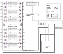
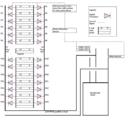
The COTS components that make up the streamlined inverter consist of, the DC power source (or battery storage source), electrical wires of the gauge required by the National Electric Code (NEC) for the current anticipated to flow through them given the voltage drop of the installed segments, Transistors connected to both sides of the DC devices and a microprocessor. The microprocessor would include a device that can detect the phase of the utility that the DC to AC source will be connected to. (Fig. 1 and Fig. 2 show the arrangement of components)
The microprocessor connected to the bank of DC batteries or solar panels will monitor the phase of the existing utility continuously. Whenever there is some prescribed (pre-programmed) minimum voltage available on the DC devices and the unit is programmed to provide power the microprocessor would function to allow that load to be connected in parallel to the AC load or utility.
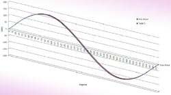
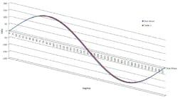
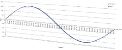
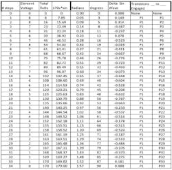
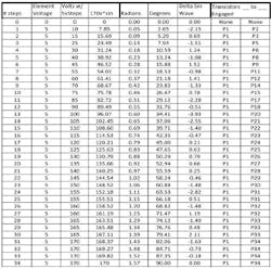
The basic operation would consist of the microprocessor sequencing low voltage control signals to the correct Transistors to produce the aggregate output from the DC source to match the AC grid as indicated in Fig. 3 and Fig. 4 for their respective systems. This variation in the serially connected DC load would then closely match the voltage on the AC load that it would be in parallel with. The output for Table 1 and Table 2 are plotted against a true Sine wave to illustrate the minimal variation that would be seen by loads on the devices in parallel to the utility.
Note, three phase power can be produced by placing three equal sized banks of DC devices, of the required phase to phase peak voltage, on the same circuit along with a common natural line and program the microprocessors to create the first phase and then shift the remaining banks 1/3 of a cycle respectively from the first.
There are countless arrangements of voltages and frequencies that can be achieved, both US standard 60hz power and the European standard 50hz. For instance the combination of devices indicated in Fig. 2 utilizes DC devices of the same size and is modeled after traditional solar panels. A second combination of devices is presented. Fig. 1 shows a system with DC devices of various sizes designed to more closely track a True Sine wave.
The Streamlined Inverter can also be used to vary voltage, with the microprocessor programmed to eliminate some banks, the remainder would adjust to maintain a slightly longer time on the bus and produce a lower RMS voltage at the same frequency.
By providing additional transistors and segmenting the individual components each transistor will only switch states 240 times a second. This reduction is a factor of 100 from traditional inverters, reducing harmonics and heat in the process. A greater percentage of electrify would be placed on the load side of the grid in lieu of lost through in-efficiencies inside the inverter itself.
Potential disadvantages of utilizing this method include a reduction in reliability; there are a total of 68 transistors which could be a point of failure. Additionally, the microprocessor can also be a point of failure; however a redundant microprocessor with a status relay to transfer operation to the back up in the event of failure can be utilized to provide additional reliability.
The proposed inverter in Fig. 2 does not track a True Sine Wave as closely as the inverter shown in Fig. 1. However, the inverter represented by Table 2 will ensure that each bank of devices is exposed to the load side of the utility for an equal amount of time (exactly 50% time on / 50% time off) the bus and has a constant switching frequency for each element.
Experimental data is required to determine which trade off would be preferable when comparing and contrasting the two proposed methods. The inverter illustrated by Fig. 1 will produce power that is more seamlessly integrated into existing utilities. The inverter illustrated by Fig. 2 would have equal components and would not require battery and solar banks to be manufactured in several sizes, reducing the shelf cost of replacement parts, and minimizing the risk of installation and wiring mix ups affecting performance.
The next step to implementing this alternate method for inverting DC power to AC is to conduct the research regarding the intermittent placement of the DC source on the AC load side of the bus and verify what offset in nameplate capacity would be required to achieve the output voltage prescribed on Tables 1 and 2 to accurately match the utility load.
Google wants to minimize the size and cost of inverters. The technique described above may prove to be a viable method. Progress depends on building, testing, improving and learning what doesn’t work and finding what does. With all the effort focused on alternative energy, the need to invert DC solar power and store renewable for future use grows each day.
