Arc Fault Circuit Interrupters Detect And Mitigate Effects Of Arcing Faults
Electronics is coming to the aid of residential utility power systems. This help is in the form of Arc Fault Circuit Interrupters, or AFCIs. These devices include electronic and electrical circuits that decide when to cut power if arcing occurs in a home’s electrical system.
Related Articles
- Controllers Guard Against Arc Faults
- Fuses Mitigate Arc Flashing
- Transient Blocking Unit Circuit Protects Electronic Systems
- Three-Terminal GDT Protects Against Fast-Rising Transients
- Reconfigurable DC Arc Detect Reference Solution
This marriage of electronic and electrical circuits originated because of the threat of arcing in a home’s electrical distribution system. Over 40,000 fires have been attributed to home electrical distribution systems in the U.S. Every year these fires result in more than 300 deaths and over 1,400 injuries. In 1996, $680 million in property loss was attributed to home electrical distribution fires. Arcing faults are a major cause of electrical wiring fires. A 1994 insurance company survey of 660 electrical fires concluded that over 33% of these fires resulted from arcing conditions.
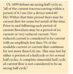
A major design consideration was the ability of the AFCI to discriminate between “good” and “bad” arcs. “Good” arcs are characterized by being periodic or repetitive (occur each 60 Hz cycle) and can be non-sinusoidal. “Bad” arcs are characterized by non-periodic or non-repetitive waveforms.
AFCIs use electronic detection circuits to discriminate between good and bad arcing conditions. Once an unwanted arcing condition is detected, the control circuitry in the AFCI trips the internal contacts, thus de-energizing the circuit and reducing the potential for a fire to occur. Methods for the detection of “bad” arcs include looking at certain frequencies, discontinuities, and inconsistencies in the current waveform. For detection, both magnitude and duration of a particular half cycle are required. Some detection algorithms also look at rising or falling edges ofan arcing current for their detection criteria. The industry voluntary standard for AFCIs requires a trip if 8 half cycles of arcing occur within a 0.5 second window.
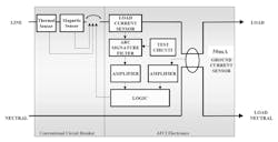
Fig. 1 shows a block diagram of a single pole AFCI circuit breaker. AFCI electronics function independently from thethermal and instantaneous sensing functions of the conventional circuit breaker. AFCI electronics detect current flow from the load terminals with the use of a load current sensor; either a resistive or magnetic sensor. The output of the load current sensor is fed into an arc signature filter that passes frequency components of arcing waveforms while rejecting other power line frequencies. The arc signature filter output is amplified and fed into a logic circuit that determines if an unsafe condition exists. Both amplitude and duration are used to detect the unwanted arcing condition. If the logic determines that the load must be de-energized, a signal fed to a triac drives a solenoid that opens the circuit breaker contacts.
The AFCI also uses a ground current sensor (typically 30 mA) for “pre-arcing” detection and protection. This sensor allows the AFCI to detect slowly-developing insulation breakdown that typically precedes line-to-ground and line-to-neutral arc faults. Additionally, lower level series arcing may become a fault to ground in three-wire systems or systems that are grounded. Theground current sensor output is amplified and fed into the logic circuit. If the logic determines that the magnitude and duration of the ground fault is hazardous, the solenoid opens the circuit breaker contacts.
AFCIs include a test circuit to ensure that the arc fault detection circuit is functioning properly. The test button generates a signal similar to an arcing output waveform of the load current sensor. The test button de-energizes the circuit if the device is functioning properly.
An AFCI circuit breaker can be combined with personnel level GFCI (ground fault circuit interrupter) protection by lowering the threshold of the ground current sensor to 6 mA. A second test circuit is required to test the GFCI function in the combination AFCI and GFCI device. Also, the grounded neutral protection is required per UL 943, Standard for Ground Fault Circuit Interrupters.
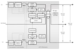
Fig. 2 is a block diagram of a two-pole AFCI circuit breaker. This device can be used on a variety of circuits including 3-wire, 120/240 Vac circuits, 120 Vac shared neutral circuits, or 240 Vac circuits obtained from a 120/240 Vac source. The shared neutral circuit, also referred to as a “home run” or “multi-wire branch” circuit, is a common household wiring technique that uses one three-conductor plus ground cable instead of two separate two-conductor plus ground cables to feed two branch circuits. Many electricians use this practice in order to save labor and material costs. These applications must use a load current sensor, arc signature filter, and amplifier for each of the phases, L1 and L2. Although the logic circuit determines if a circuit needs to be de-energized, both phases must be de-energized, because the fault may be in the three-conductor plus ground cable. The device requires two test circuits, one for each phase. The ground current sensor uses all three conductors to sense leakage currents, and both circuits trip.
Like the single pole system, combination AFCI and GFCI, a two-pole AFCI circuit breaker can combine personnel GFCIprotection. Like the single-pole version, an extra test button is required to test the GFCI function of the combination AFCI/GFCI. The AFCI circuit breakers described above use analog circuits with custom chips or ICs to perform some of the circuit functions.
You can achieve similar arc detection technologies using a digital approach. The digital AFCI can use the same current sensor and ground current sensors. Both the current signal and the ground current signal are amplified and converted into a digital signal with an A/D converter. The microprocessor then calculates the line current and the irregularities in the current signals using special software algorithms to determine if arcing is present. If the microprocessor determines that the load must be de-energized, a signal is fed to a triac used to energize a solenoid that opens the circuit breaker contacts. As in analog circuits, a custom IC can be used to reduce the required space of the digital circuitry. The digital approach allows for easier algorithm changes in the development process and increased flexibility in the testing process.
Existing AFCIs do not detect another cause of electrical fires– the glowing connection – unless an arc or ground fault is also present. A glowing connection is a special case of a high resistance connection that can dissipate a considerable amount of energy and glows to the point of incandescence.
Besides their heat output, glowing and other poor connections are manifested by excessive voltage drop across the connection. The magnitude of the voltage drop varies with the impedance of the connection and the load current. (The impedance of the circuit will also have an effect on the ability of a conventional circuit breaker to instantaneously trip when the short circuit current is below the instantaneous trip threshold.) The AFCI will detect some of the secondary effects of the glowing connection, such as arc faults and ground faults. By detecting these secondary effects, the AFCI can eliminate a critical factor in further destruction – the flow of electric current.
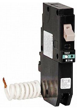
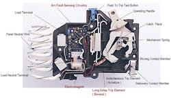
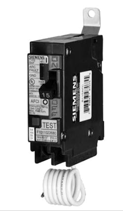
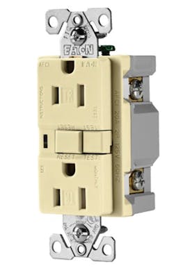
AFCI products can mount in the home’s main breaker box or in a wall receptacle. Fig. 3 is an AFCI from Eaton and Fig. 4 shows and internal view of the device. Fig. 5 is a Siemens AFCI; both of the Eaton and Siemens AFCIs mount in the main breaker alongside other circuit breakers. Fig. 6 is a wall receptacle from Eaton.
For additional information on AFCIs, you can visit www.afcisafety.org.
Website content is provided by members of the National Electrical
Manufacturers Association LVDE AFCI Task Force.
Reference
New Technology for Preventing Residential Electrical Fires:Arc-Fault Circuit Interrupters (AFCIs), Douglas A. Lee, Andrew M. Trotta, William H. King, Jr., Consumer Product Safety Commission.

