Design a PFC Resonant Coupled Inductor That Doesn’t Distort Power Factor
Over the past 40 years many of my designs included Power Factor Correction (PFC) ranging from 50 W to over 5.0 kW and operating from 30 kHz to 150 kHz switching frequency, utilizing CCM, CrCM and DCM modes and 50 Hz to 850Hz input power.
Recently, I was designing a PFC unit for 800 Hz operation and had difficulty designing the input filter that eliminates EMI, but does not distort the power factor caused by the large currents in the X capacitors. My challenge was that I could not divert the switching current from the input filter and circulate it in another loop. Then I remembered Lloyd Dixon’s seminars for Unitrode that covered coupled inductors and “current steering”. That is what I needed but did not understand the theory at that time. So I went back and searched the many papers on the subject, finding lots of higher math and transformer equivalent circuits. There is a coupled inductor where one winding has only AC current and the other with DC current. Why were they all using transformer circuits to describe this coupled inductor? In transformers, current goes in the primary dot and out the secondary dot. This design has the current being shared (split into ac and dc) by the primary and secondary.
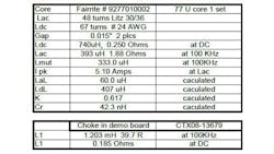
So back to the bench, declaring that if two inductors share the same core the inductance is either mutual or leakage. I measured the total inductance of each inductor and their mutual inductance, and Figure 5 (see all figures below):
Ldc = Lm + LdL (1)
Lac = Lm + LaL
Where:
Ldc = Total inductance of dc winding
Lm = Mutual inductance between LAC and LDC windings
Lac = Total inductance of ac winding
LdL = Leakage inductance in the LDC winding
LaL = Leakage inductance in the ac winding
Using SPICE simulation, I realized the simplicity of this inductor configuration. If this is true, then why is it not in general use, why can’t I buy these Resonant Coupled Inductors (RCIs) off the shelf? The PFC Inductors I can buy are single windings of high power dissipation due to high resistance at the switching frequency (Rac losses). The designer did not have a good understanding of skin effect nor proximity losses. I believe that the previous papers have made this design very difficult to understand and scared off the engineers and magnetics manufacturers. This is not just about PFC inductors but input and output filters. Any place we have an ac and dc current component in an inductor winding, we should look at this topology to reduce the filter components.
To meet this design problem I came up with a solution and patented it. The RCI patent is currently pending (US 62/170,844) and the search results are very promising. I would like to hand off this design to the right company. Why did I patent this configuration when so many papers have been written on it? Yes, there is lots of prior art but the theory given is very confusing. Maybe I can educate the engineering community and reap some small benefits.
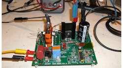
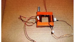
This design has been simulated in SPICE and bench tested on a T.I. Eval board. The Eval’s improvement was evident and all readings and waveform match the SPICE simulation. There is no magic, just solid engineering.
Patent Features:
- The RCI will divert >30db of switching current from the input filter.
- The resultant magnetic package is about the same volume as a standard PFC inductor but in a lower profile that aids system packaging, thermal flow and noise shielding.
- Due to the separation of ac and dc currents, a higher efficiency unit can be made in the same volume.
- Manufacturing costs are similar to a PFC inductor.
- Core magnetics with some needed cutting are readily available.
- This device will operate in CCM, CrCM and DCM of operation.
- Can be used in any topology, input or output, diverting switching current to ground.
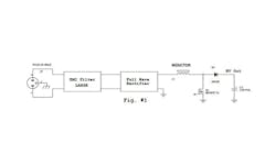
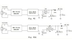
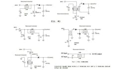
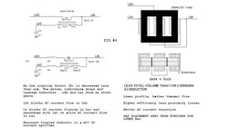
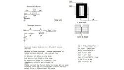
Figure 1 is prior art for reference only. Figure 2 shows both a two-winding and three-winding PFC circuit to help explain the RCI operation, but there can be many implications as shown in Fig. 3.
In Fig. 4, L2 has three windings and in Fig. 5, L2 is a two winding device. Both two- and three-winding devices operate in the same manner as explained below:
Ldc and Lac, which when loosely coupled (0.5< K<0.90) each form a leakage inductance. (LdL + LaL) that reduce their original (K=1) inductance such that:
Ldc = Lm + LdL (2)
Where:
K = Magnetic coupling factor
And:
Lac = Lm + LaL (3)
Where:
Therefore:
Ldc > Lac for best results
Lm = K (Lac × Ldc)0.5
K = Lm/(Lac × Ldc)0.5
Cr = Resonant capacitor
LdL impedes the flow of ac current to the external circuit, but has low resistance to Idc, current in the dc winding. LaL resonates with the resonant capacitor (Cr) to form a low-impedance series resonant circuit at the switching frequency and shunts the ac current to ground, away from the output and the IDC current is blocked by Cr. The ac winding carries high ac current so its resistance at the switching frequency (Rac) must be constructed as low as possible, so Litz wire is sometimes used. The dc winding only requires a low dc resistance, so normal wire is used. The placement of core gaps is also important to Rac.
Ldc > Lac improves the ac rejection ratio at the operating frequency of Iac (current in ac winding). As the K factor is reduced, Lm gets smaller and the leakage inductances get larger. As Lm is reduced, the IAC component increases, affecting the external circuit. A K of ~0.6 is a good tradeoff.
The ac winding is sized according to the needs of the converter, which is known by those in the art. It has typical values of 500µH to control ripple current in the winding and switching device.
A low coupling factor (K) is obtained by placement of the two windings on opposite sides of the core and gap. The gap should be placed away from the windings or the fringing flux will increase winding resistance. Prior art coupled inductors were composed of one winding containing both ac and dc currents. This caused the winding to be large and difficult to package and keep cool. This unit with its smaller dual windings or triple windings can be packaged in a lower profile package, allowing better thermal flow. Full complete winding rows offer the best results.
Resonant Capacitor Calculations
Determine this capacitor value to resonate with Lac, leakage inductance.
1. Using an LCR meter, measure LAC, Ldc, and Lm. You can directly measure Lm with most LCR meters with four leads. Attach the drive leads across Ldc, the sense leads across Lac and read Lm directly. The sign displayed is the phase.
2. LaL= Lac – Lm
Use LaL to calculate Cr at the switching frequency:
Cr = 1/[(2pF)2 × LaL] (4)
It is important to note that a custom device is not necessary to get good results. You could obtain a coupled inductor (K>0.95) that has suitable ac and dc windings with the inductance to maintain proper PFC operation. Then add a low-frequency inductor (Powder Iron to operate at 120Hz) to connect the dc winding to the bridge. Then add a high-frequency (Ferrite) core to the ac winding and terminate with the resonant capacitor. These three devices would simulate the RCI. Not a pretty package, but a good start in understanding this topology.
The word PFC (Power Factor Correction) is used throughout this document to denote one configuration that is widely known to the profession, but the RCI can be used in many different configurations as shown in Fig. 3 in both two and three winding packages. Additionally, any electronic device that draws more than 25 Watts off line should be power factor corrected. The RCI will scale from 25 watts to kW and it will operate from 50Hz to over 850 Hertz, filling the needs of commercial and military devices.
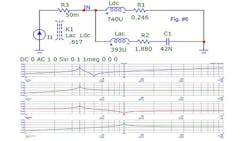
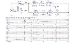
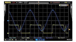
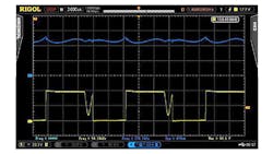
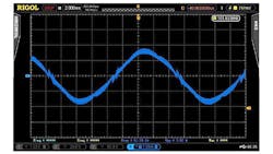
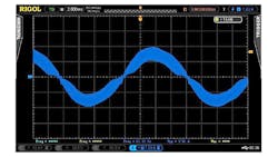
Figures 6 and 7 are SPICE simulations for the RCI. Figures 8 to 14 are data taken from a TI UCC3817 (250W) demo board rev 5 with the original TI inductor (L1) and a two-winding RCI.
