How to Easily Design Power Supplies (Part 2)
This article is part of the Power Management series: How to Easily Design Power Supplies
Members can download this article in PDF format.
What you'll learn:
- What other topologies are used for SMPS beyond the three most common types?
- Common and advanced isolated topologies.
- What is the switched capacitor converter?
Beyond the three basic, nonisolated switch-mode power-supply topologies discussed in Part 1, many more topologies are available. However, they all require additional power components, which typically makes them higher cost and lowers their power-conversion efficiency. With certain exceptions, adding additional components in the power path will generally add losses.
Some of the most popular topologies are SEPIC, Zeta, Ćuk, and the four-switch buck-boost. They each offer features not available with the three basic topologies. The most important features of each topology include:
- SEPIC: The SEPIC can generate a positive output voltage out of a positive input voltage that may be higher or lower than the output voltage. Boost regulator ICs may be used to design a SEPIC power supply. The drawback of this topology is the need for a second inductor or one coupled inductor and a SEPIC capacitor.
- Zeta: The Zeta converter is similar to the SEPIC, but it’s capable of generating a positive or negative output voltage. In addition, it doesn’t have a right-half-plane zero (RHPZ), thereby simplifying the regulation loop. A buck-converter IC can be used for such a topology.
- Ćuk: The Ćuk converter offers an inversion of a positive input voltage into a negative output voltage. It uses two inductors, one on the input side and one on the output side, making it quite low noise on the input and output sides. The drawback is that only a few switch-mode power-conversion ICs support this topology, since a negative voltage-feedback pin is required for the regulation loop.
- Four-switch buck-boost: This converter type became quite popular in recent years. It offers a positive output voltage from a positive input voltage. The input voltage may be higher or lower than the adjusted output voltage. This converter replaces many SEPIC designs, as it offers higher power-conversion efficiency and only requires one inductor.
Most Common Isolated Topologies
Besides nonisolated topologies, some applications require galvanically isolated power converters. The reasons may be safety concerns, the need to have floating grounds in larger systems where different circuits are interconnected, or the prevention of ground current loops in noise-sensitive applications. The most common isolated converter topologies are the flyback and forward converters.
The flyback converter is typically used for power levels up to 60 W. The circuit operates in a way that during the on-time, energy is stored in a transformer. During off-time, this energy is released to the secondary side of the converter, powering the output.
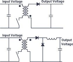
This converter is simple to build, but it requires relatively large transformers to store all of the energy necessary for proper operation. This aspect limits the topology to lower power levels. Figure 1 shows a flyback converter on the top and a forward converter on the bottom.
Besides the flyback converter, the forward converter also is very popular. It uses a transformer differently than the flyback. During the on-time, while there’s current flow through the primary-side winding, current also flows through the secondary winding.
Energy should not be stored in the core of the transformer. After each switching cycle, we must make sure that all of the core’s magnetization is released to zero, so that the transformer will not saturate after a number of switching cycles. Such an energy release out of the core can be achieved with a few different technologies. One popular way is to use an active clamp with a small additional switch and capacitor.
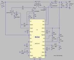
Figure 2 shows the LTspice simulation environment schematic of a forward active clamp design using the ADP1074. In the forward converter, there’s an additional inductor in the output path compared to the flyback (Fig. 1, again). Though it’s one additional component with associated space and cost implications, it helps to generate a lower-noise output voltage compared to a flyback converter. Also, the transformer size needed for a forward converter at the same power level as a flyback may be much smaller.
Advanced Isolated Topologies
Besides the flyback and the forward topologies, there are numerous transformer-based galvanically isolated converter concepts. The following list offers basic explanations about the most common of these converters:
- Push-pull: The push-pull topology is similar to the forward converter. However, instead of one low-side switch, this topology requires two active low-side switches. Also, it requires a primary transformer winding with a center tap. The advantage of the push-pull is an operation with generally lower noise compared to a forward converter. In addition, it needs a smaller transformer. The hysteresis of the BH curve of a transformer is utilized in two quadrants rather than just one.
- Half-bridge/Full-bridge: These two topologies are typically used for higher power designs from a few hundred watts up to a few kilowatts. They require high-side switches in addition to low-side switches but enable very high power transfer with relatively small transformers.
- ZVS: The term zero voltage switching (ZVS) comes up often when discussing high-power isolated converters. Another term for such converters is LLC (inductor-inductor-capacitor) converters. These architectures aim for very high efficiency conversion. They generate a resonance circuit and switch the power switches while the voltage or current across the switches is close to zero, thus minimizing the switching losses. However, such designs may be difficult to design and the switching frequency isn’t fixed, sometimes yielding EMI problems.
Switched Capacitor Converters
In addition to linear regulators and switch-mode power supplies, there’s a third group of power converters—switched capacitor converters. They’re also referred to as charge pumps. Switched capacitor converters, which use switches and capacitors to multiply or invert voltages, offer the big advantage of not needing any inductor.
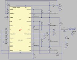
Typically, such converters are employed for low power levels of below 5 W. However, recent advances have allowed for much higher power switched capacitor converters. Figure 3 shows the LTC7820 in a 120-W design at 98.5% efficiency, converting 48 V to 24 V.
Part 3 this series will cover digital power supplies, EMI considerations, filtering, and silent switchers.
Read more articles in the Power Management series: How to Easily Design Power Supplies


