The duty cycle of a step-down switching regulator (buck converter) corresponds to the output voltage divided by the input voltage in continuous-conduction mode (CCM). Therefore, if the output voltage is exactly half the input voltage, this corresponds to a 50% duty cycle. For real components and the corresponding parasitic losses, the duty cycle is slightly different. However, the simple formula for the duty cycle is sufficient as an approximation.
Therefore, if an output voltage of 1 V is to be generated from a supply voltage of 5 V, it corresponds to a 20% duty cycle. Figure 1 shows a step-down converter topology with an ADP2389 regulator from Analog Devices. This regulator can switch with a switching frequency of up to 2.2 MHz.
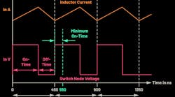
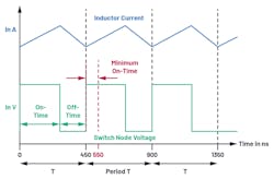
The minimum on-time of the ADP2389 is 100 ns. Accordingly, a voltage conversion of 5 V to 1 V isn’t possible at a switching frequency of 2.2 MHz. It would require a duty cycle of 20%, which corresponds to an on-time of just 90 ns for a period of 450 ns. This time lies below the minimum specified on-time of the ADP2389 voltage converter.
If the ADP2389 should nevertheless be used to convert 5 V to 1 V, the switching frequency can be slowed down. Through this, the period T from Figure 2 becomes longer and the minimum on-time, at 100 ns, becomes lower in terms of percentage. For a set switching frequency of 2 MHz, the period is 500 ns. For the required 20% duty cycle, an on-time of 100 ns is required. According to the specifications, this is possible with an ADP2389.
The question arises of why there’s even a minimum on-time that restricts the possible ratio of input voltage to output voltage. In many switch-mode power converters, the reason lies in the fact that the coil current is measured during the on-time. This current is used for overcurrent protection and in regulators that work according to the current closed-loop control principle (current-mode control). The measured inductor current is also needed for the loop regulation.
After a switching transition, the generated noise must first subside before a quality current measurement can be made. This takes some time, which is known as the blanking time. Especially for very high switching frequencies of several megahertz, the length of the minimum on-time is taking on an ever-greater role and circuits are being developed to enable a very short minimum on-time.
For low duty cycles, such as high input voltage and low output voltage in a stepdown switching regulator, the minimum possible on-time is a critical limitation. It frequently limits the maximum switching frequency at which a switch-mode power supply can be operated.
Frederik Dostal is Senior Staff Field Applications Engineer at Analog Devices.


