What you’ll learn:
- A close look at SiC’s benefits.
- How to improve three-phase inverters for variable motor drives.
The most important development in power electronics in recent years is the rise of so-called wide-bandgap (WBG) materials, namely silicon carbide (SiC) and gallium nitride (GaN). The properties of WBG materials promise smaller, faster, and more efficient power electronics.
WBG power devices are already making an impact on a wide variety of applications and topologies, from common power supplies and chargers to solar power and energy storage. Silicon carbide has been in the market with power devices longer than GaN and is typically used for higher-voltage, higher-power applications.
Motors make up a considerable fraction of total power used in industrial applications. They’re used for HVAC, heavy-duty robots, material handling, and many other functions. Improving the efficiency and reliability of the motor drives is an important way to reduce costs. To meet such challenges, designers are turning to SiC—its unique properties are making it the power electronic material of choice in high-power industrial drives.
SiC Material Properties
Silicon carbide is a semiconductor material with a larger bandgap (3.26 eV) than silicon (1.12 eV) and has a number of favorable properties for power electronic devices.
SiC has a 10X higher dielectric breakdown strength than silicon (Fig. 1). One of the most important functions of a power electronic switch is to hold off high voltages. Because of the high dielectric strength, SiC supports high voltage in a shorter distance through the device. This distance is also the drift region between the channel and drain contact in a vertical device. The shorter drift region reduces the electrical resistance of the device and directly yields low power losses.
The wide bandgap also reduces the number of thermally excited carriers and results in less free electrons and lower leakage current. In addition, the leakage current is small and stable over a much larger temperature range than traditional Si devices. This makes SiC MOSFETs and diodes a more efficient choice for high-temperature applications.
Thermal conductivity in SiC is 3X higher than that in silicon, allowing for greater heat dissipation. Removing heat from power electronic devices is a very important part of the system design. SiC’s thermal conductivity results in lower operating temperatures and thermal stress on the switches.
Finally, SiC has twice the electron saturation velocity of silicon, enabling faster switching speeds. A faster switch has lower switching losses and can work at higher pulse-width-modulation (PWM) frequency. In some power-conversion topologies, a higher PWM frequency allows for smaller, lighter, and cheaper passive elements, which are often the largest and most expensive parts of the system.
The process of creating a SiC wafer—the raw material of semiconductor devices—is much more challenging than creating Si wafers. While a silicon boule can be pulled from a melt, SiC boules must be grown in a vacuum chamber by chemical vapor deposition. It’s a slow process and difficult to grow with an acceptable number of defects. Silicon carbide is a relatively hard, brittle material (often used for industrial cutting), and therefore, requires special processes to slice wafers from the boule.
ON Semiconductor has multiple supply agreements for SiC substrates to ensure capacity as SiC demand grows. In addition, the company is developing an internal supply of SiC substrates.>
Improving Three-Phase Inverters
The traditional solution for variable-speed high-voltage motor drives has been the three-phase inverter that has silicon IGBTs co-packed with anti-parallel diodes to support the motor current commutation. The three half-bridge phases drive the three-phase coils of the inverter to deliver a sinusoidal current waveform and drive the motor.
There are several ways to upgrade the performance of this system using SiC. The energy wasted in the inverter is composed of conduction losses and switching losses. SiC devices can influence both of these loss mechanisms.
It’s increasingly common to replace the anti-parallel silicon diode with a SiC Schottky barrier diode. The Si reverse diode has a reverse-recovery current, which increases switching loss and generates EMI. The advantage of the SiC diode is that it has almost no reverse-recovery current, reducing switching losses by up to 30% and possibly reducing the need for EMI filters. Also, the reverse-recovery current adds to the collector current at turn-on, so a SiC diode reduces the peak current through the IGBT, increasing system reliability.
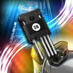
The next step in improving inverter efficiency is to replace the IGBT fully with a SiC MOSFET (Fig. 2). The SiC MOSFET reduces the switching losses by up to a factor of five, further boosting efficiency. Depending on the device selection, the conduction losses of SiC MOSFETs can be half that of Si IGBTs of the same current rating.
The efficiency improvements result in less waste heat to be dissipated. In turn, designers are able to reduce costs by shrinking the cooling system or eliminating active cooling altogether. As a result, the smaller motor drive can be mounted directly on the motor housing, shrinking the cabling and motor-drive cabinets.
WBG devices switch fast, which lowers the switching losses but brings other challenges. The high dV/dt produces noise and can stress the motor-winding insulation. One solution is to slow down the switching using a gate resistor, but then the switching losses rise back up toward the level of the IGBT. Another solution is to place a filter on the motor phases; the filter size shrinks with increasing PWM frequency, introducing a tradeoff between heat and the filter cost.
Fast switching power devices don’t tolerate stray inductance and capacitance in the inverter circuit. The so-called “parasitic” inductance can lead to voltage spikes due to the high transients generated during switching. To eliminate parasitics, make sure that the printed-circuit-board (PCB) layout is done correctly. All power loops and traces should be short and devices placed close together. Even the gate-drive loop should be carefully minimized to reduce the chances of unwanted device turn-on due to noise.
Power modules integrate multiple devices together in the correct topology for motor drives (among others), providing a faster solution with low parasitic inductances and optimized layout. The power module saves PCB area and makes thermal management easier by reducing the number of parts that need to be attached to the heatsink.
Conclusion
The fast switching and reduced losses of silicon-carbide devices make them an important solution for efficient, integrated motor drives. As we discussed, system designers can shrink motor drives and move them closer to the motor to reduce costs and improve reliability. The growing array of devices and systems offered by ON Semiconductor for SiC motor drives helps deliver the right solution for a wide variety of industrial applications.


