EMI Reduction in Automotive Power Converters
This article is part of the TechXchange: Delving into EMI, EMC and Noise
Members can download this article in PDF format.
What you'll learn:
- How to minimize EMI in automotive architectures.
- The types of EMI that affect automotive systems, and how they originate.
- EMI effects in EV powertrains and V2X systems.
This article will discuss electromagnetic-interference (EMI) mitigation techniques as they relate to the optimum performance of vehicle system architectures. Critical areas in vehicles can be highly affected by EMI and lead to subpar electronic circuit performance, especially in automotive power supplies, which are at the heart of an overall vehicle electrical/electronic system.
Covered here will be EMI filtering and other system techniques that can be integrated into the system architecture to minimize RF EMI interference, both conducted and radiated. These should help designers pass EMI standards testing in their respective regions.
Emissions Standards
The automotive industry and individual automobile manufacturers must meet a variety of electromagnetic-compatibility (EMC) requirements. Regulatory compliance to EMC standards, CISPR 25 for automotive applications, is critical in a product design. For example, two requirements are to ensure that electronic systems don’t emit excessive EMI or noise, and be immune to the noise emitted by other systems.
The efforts required to achieve compliance affect both product development costs and time to market. CISPR 25 is one of the most stringent international emission standards for vehicles and devices targeting radio disturbance characteristics. The limits and methods of measurements are intended to protect onboard receivers from disturbances produced by components, such as a switching regulator in a power-supply design.
Designers need to fully understand CISPR and other emission standards before they begin their power designs (see References 2 and 3).
Types of EMI
To reduce EMI in a design, engineers first must understand how EMI propagates into a design. EMI has two main classes—conducted and radiated—that can lead to longer design time to market and added cost. The design efforts, to lower EMI to a level that will pass EMI standards for areas or countries in which a product would be used, are crucial in creating a successful functioning design.
Conducted EMI is typically coupled via cables and physical conductors such as power connections, parasitic impedances, as well as ground connections. Radiated EMI gets coupled via radio transmission sources through the air due to electric fields (capacitive coupling) or magnetic fields (magnetic coupling).
Switching voltage regulators will usually be one of the main culprits of EMI generated within an automotive system or generated externally.
Origins of EMI
Electronic circuitry usually has current flowing from a source to a load and returning back to the source in a loop. Loops have inductance and a varying current through components, wires, or PCB traces. When current varies within the loop, it will generate a proportional voltage. The loop has a self-inductance and the rate of current change will be di/dt due to current demand in the load. When the current changes quickly in the loop, it will generate a voltage spike.
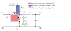
To minimize a spike, designers can shrink the loop area, which will reduce the loop inductance. The power IC can use two input loops in parallel that result in effectively half the parasitic loop inductance5 (Fig. 1). Designers can employ bypass capacitors strategically located close to ICs and other devices to minimize EMI as well.
Good ground planes will provide low-impedance paths for such components as bypass capacitors. Designers can keep noisy switching nodes or oscillators as far away as possible from sensitive nodes on the PCB. Good ground areas or planes also may serve as shielding or physical separation from noisy areas or components like switch nodes/power transistors, high di/dt capacitors, and inductors.
Some other methods will help reduce radiation in the loop, too. One example would be a design using a discrete buck regulator with switching power FETs. The drive signal to the FET can be slowed down by adding a gate resistor, which may help meet the tough radiated emissions standards for automobiles. The downside to this method is that the design now loses some efficiency, adds a component, and increases board footprint.
EMI in Automotive Wiring Harnesses
Advanced automotive electronic-control technology has led to added electronic equipment in the vehicle. Frequencies and power have gradually increased in the vehicle, creating a denser atmosphere of electromagnetic waves. This will greatly contribute to EMI in the vehicle, thus disturbing electrical/electronic equipment and possibly damaging electrical/electronic components.
Automotive wiring harnesses, one of the highest contributors of EMI in the automobile, also may be affected by EMI.
Designers can take some measures to minimize EMI effects by shielding source equipment and their respective wiring harnesses. Conducted and radiated EMI can be minimized in longer harnesses by adding an improved filter. Careful planning of the wiring harness also will help by arranging lower power circuitry closer to the signal source and higher power interfering circuitry closer to the load.
Improved grounding techniques will also help reduce EMI in automotive harnesses. Shielding harnesses and connecting to the car body is a good means of reducing EMI interference.
Reduction of Radiated and Conducted EMI in the Automobile
Figure 2 shows EMI bands of interest and mitigation techniques.7
Radiated EMI in non-isolated power converters in the automobile
Radiated EMI is caused by common-mode noise in the vehicle power cables, which radiates into the vehicle space. This noise is mostly radiated by non-isolated power converters via the switching power devices within that power converter. Higher switching frequencies in modern power supplies and efforts to reduce power converter physical sizes are the main contributors to EMI in the automobile (Fig. 2, again).
Conducted EMI in an automotive buck converter
Designers may find that passing the FM band limit in CISPR 25 Class 5 is quite challenging.6 That’s because the EMI filter worsens at high frequencies. Near-field coupling also will degrade EMI filter performance because high-frequency noise generates powerful magnetic and electric fields that will couple into the input of an EMI filter.
Some solutions that designers may want to try include:
- Reducing the noise source by adding a boot resistor or snubber, or decreasing the switching frequency (this will decrease the high-frequency harmonics of the noise source).
- Reducing the power-switch (SW) capacitive parasitics by placing as little PCB SW copper as possible, while also considering the thermal dissipation.
- Adding a shielding case will reduce electrical-field coupling.
- Adding filter components—a common-mode choke can be incorporated, but this will increase system cost.
Employing an EMI filter at the input of the buck converter, as well as a careful layout, will help, too. And an iron shielding box can be a last resort (see Reference 6).
Components to Help Minimize EMI
Often, the simplest components turn out to be the most important. Chip ferrite beads can be designed into the electronic system, enabling full current handling up to 85°C. The small size of ferrite beads allows them to provide EMI protection in even the most densely populated PCBs.
EMI-suppression film capacitors, qualified to the AEC-Q200 (rev. D) and IEC 60384-14: 2013/AMD1: 2016 grade IIB quality standards, can act as EMC filters for automotive power inverters.
EMI in the EV
Electric powertrains (EPTs) are major contributors to wideband, high-level EMI. It will intrude upon susceptible electronic and RF systems like those in connected vehicles, infotainment, advanced driver-assistance systems (ADAS), and autonomous-driving systems. EMI management is especially critical in these systems.
EMI in Vehicle-to-Everything (V2X)
With wireless networking using 5G and V2X technologies, future EVs will transmit, communicate, and process far more data, over low-voltage networks, than today’s vehicles. The automotive industry is pushing the envelope regarding battery capacity, range, engine power, and fast-charging technologies, all of which use high current and power levels. These high power/current levels will emanate strong electromagnetic fields that need to be addressed in the architecture of all electrical components.
EMI mitigation is critical to the reliable and safe operation of low-voltage networks with potentially susceptible electronic and RF units due to the presence of the power inverter in the EPT. The inverter, operating at high power and fast switching frequencies, generates rapid voltage and current transients that are the major source of conducted and radiated EMI.
In V2X automotive communication applications, passive components also play an important role. No matter how complex the semiconductors, without EMC components, transient protection, high-frequency connectors and antennas, V2X would not be possible.
Summary
Switching power supplies in automobiles will need some form of input filtering to pass EMI standards such as CISPR 25 or other regions’ EMI regulations. Other forms of minimizing EMI in the automobile were discussed in this article as well, and most likely will need to be incorporated in many design architectures to achieve standards approval.
So many methods are available to help tame EMI encroachment into automotive electronics. Most designers will use more than one method, and some will use multiple or all methods. Time-to-market is critical for these automotive power designs and the EMI testing must be done when the overall design is fully complete.
As we move forward from gasoline-powered vehicles to electric vehicles, and on to the autonomous vehicle, we will need to modify, as well as add, new and innovative EMI-mitigating techniques to pass compliance testing in a timely manner. More creative techniques will emerge as we venture into the future of automotive electronics.
Read more articles like this at the TechXchange: Delving into EMI, EMC and Noise
References
1. Understanding Noise-Spreading Techniques and their Effects in Switch-Mode Power Applications, TI Power supply design seminar
2. An overview of conducted EMI specifications for power supplies
3. An overview of radiated EMI specifications for power supplies
4. Enhanced HotRod QFN Package: Achieving Low EMI Performance in Industry’s Smallest 4-A Converter
5. How a DC/DC converter package and pinout design can enhance automotive EMI performance
6. Reduce Conducted EMI in Automotive Buck Converter Applications
7. Advanced EMI mitigation techniques for automotive converters


