Minimizing EMI in Commercial Aircraft
This article is part of the TechXchange: Delving into EMI, EMC and Noise
Members can download this article in PDF format.
What you'll learn:
- How do portable electronic devices affect aircraft electronic systems?
- What types of PEDs cause EMI issues with aircraft equipment?
- EMI impact on aural warning systems.
- Key factors regarding shielding of cables.
The FAA advisory circular, AC 91.21-1D, “Use of Portable Electronic Devices Aboard Aircraft,” prohibits operation of portable electronic devices (PEDs) not installed aboard U.S. registered civil aircraft, while operating under instrument flight rules (IFR). The measurement of the radiated field coupling between passenger cabin locations and aircraft communication and navigation receivers, via antennas, is called interference path loss (IPL).
Boeing states that operators of commercial aircraft have reported numerous cases of PEDs affecting aircraft systems during flight. This article will delve deeply into this controversial subject of electromagnetic interference (EMI) in commercial aircraft. Let’s see what one of the largest aircraft manufacturers has to say on this subject.
We will not be discussing aircraft vulnerability to onboard intentional Electromagnetic Environmental Effects (E3) or terrorism. We will discuss EMI effects inside the aircraft from a technical point of view.
Boeing Aircraft Commentary on EMI in Commercial Aircraft
It’s been reported that many cases of PEDs have affected aircraft systems while in flight. Such devices include, but aren’t limited to, what’s listed here:
- Laptop and palmtop computers
- Audio players/recorders
- Electronic games
- Cellular phones
- CD players
- Electronic toys
- Laser pointers
These devices are suspected of causing such events as autopilot disconnect, erratic flight deck indications, aircraft going off course, and uncommanded turns.
EMI Onboard the Aircraft Due to Wireless Technology
There’s ever-increasing growth in portable wireless devices in our world, and they all could cause disruption in aircraft navigation and communication systems. Such PEDs can act as transmitters whose signals might be detected by aircraft radio receiver antennas1,5 (Fig.1).
In addition to the 20 antennas on the 787 fuselage, others are used for:
- Satellite communications
- Marker beacons
- Weather radar
- Ultra-high-frequency (UHF) distance measuring equipment (DME)
- Instrument landing system (ILS)
- Wireless local-area networks (WLAN)
- Air traffic control (ATC) and traffic collision-avoidance systems
- Terminal cellular systems
- Crew wireless LAN units
Passenger seat distances from aircraft doors
Electromagnetic waves will typically propagate and "leak" more freely from the aircraft doors than from the fuselage or small windows of the aircraft.
It’s obvious that the location of the antenna was the most important factor in determining the coupling intensities throughout the aircraft. As observed from graphical plots,5 as the distance from the antenna increased, the coupling decreased. The distance from the antenna was estimated such that if the distance was less than four seat units, the coupling would be maximum, while if the distance was greater than nine seat units, zero coupling would exist.
UWB or 5G NR devices
Wireless short-range ultra-wideband (UWB) and 5G New Radio (NR) handhelds or laptops may be a cause of EMI disturbance on an aircraft. FAA rules state passengers must turn off or put devices in airplane mode.
Aural Warning Systems
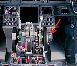
Aircraft for commercial or military use carry aural warning systems6 that will alert the pilot with audio signals for various situations. These events include the following: abnormal takeoff configuration, landing gear configuration, stall, pressurization, MACH or airspeed overspeed, an engine or wheel-well fire, calls from the crew call system, collision-avoidance recommendations, and more (Fig. 2).
The function of aural warning systems is considered critical. Thus, aircraft manufacturers are required to prove that they’re not susceptible to outside environmental threats such as thermal stress, vibrational impact, or EMI.
The aerospace industry has become more dependent on electrical and electronic systems. As such, there’s a concern to protect aircraft electrical and electronic systems from radiated and conducted susceptibility. This is sometimes called a fly-by-wire system. An aircraft’s fly-by-wire capability is critical for continued safe flight and landing.
Today’s aircraft are constructed with a significant amount of composite materials, which provide less electromagnetic shielding than the aluminum materials used for older aircraft. Modern aircraft also utilizes more data buses and microprocessors with higher processing speeds. This results in higher-density IC cards, which are more susceptible to high-intensity radiated fields (HIRF).
Aural warning system electronics, in conjunction with their circuit cards, are no exception to this modern aerospace industry trend—they may be more susceptible to HIRF than before. Moreover, the HIRF environment has become more severe due to an increase in the number, and radiated power, of RF transmitters such as radar, radios, television, and other ground-based, shipborne, or airborne RF transmitters.
Cargo Bay EMI Sources
Interference to avionics systems may lurk from sources in baggage stowed in aircraft cargo bays. It could involve devices such as electronic baggage tags, or from other inadvertent—or even intentional—transmissions from baggage. And the walls in these areas could be radio-transparent.
EMI sources in cargo bays7 may be a possible threat source to the avionics in adjacent bays, avionics in the cargo bays themselves, as well as to the CNI (communication, navigation, and identification) antennas mounted on the aircraft outer surface. Path-loss calculations and measurements are used to determine the coupling of these sources to the avionics, and susceptibility assessments can be determined depending on these calculations/measurements.
Aluminum containers in the cargo bays can’t be relied upon to provide any shielding to EMI. Thus, RF monitoring sensors in the avionics bays and/or cargo bays should be considered if potentially unsafe EMI levels exist. In addition, bulkheads between cargo bays, adjacent to avionics bays, can be coated, covered, or embedded with metal to provide a level of EMI protection.
Shielding in an Aircraft with Braided-Shield Cable
There’s a strong push underway to deploy electric aircraft in the coming generations for commercial aircraft. Electrical energy is being used instead of traditional hydraulic and pneumatic energy. This means that the onboard electromagnetic environment is becoming much more severe than in past models.
As a result, interconnecting cables—the major coupling path of EMI—are required to provide more adequate EMI protection capability.basics Shielded cables8 are considered reliable signal and power carriers and have been widely used in aircraft for years. However, any differences in shielding structure or the number of shielding layers can lead to a significant change in shielding performance.
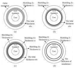
The most common aircraft cables are single-shielded cables, contact double-shielded cables, double-shielded cables, and multi-shield cables (Fig. 3).
Aircraft cables are important components of the electrical wiring interconnection system. Still, they’re susceptible to complex electromagnetic environments like thunder, lightning, and HIRF. Reference 8 determined the following:
- When the thickness of the shielding is constant, improved shielding effectiveness cannot be obtained just by dividing the shielding. However, when each shielding layer is of equal thickness, as the number of layers increases, the shielding effectiveness of the cable will improve.
- When the thickness of the inner and outer shielding layer is different, the transfer impedance of each is not equal. Also, when the ratio of the thickness between the inner and outer shield layers is larger than 1, the larger the ratio is, the better the shielding performance is, and vice versa.
- An insulating layer between the shield layers of the double-shielded cable will provide better shielding effectiveness. In addition, the thicker the insulating layer between the two shielded layers, the better the shielding effectiveness.
Summary
Aircraft operators can increase their ability to make valid decisions regarding the use of PEDs, which may create EMI disturbances, by becoming aware of the most current information in these following areas: testing and analysis of PEDs and aircraft systems, resulting regulations and recommendations, operator actions for investigating and preventing PED events, and ongoing related activities at Boeing.
Some passengers may still use electronic devices without permission on board aircraft, including cellular phones that they shouldn't be attempting to use. Pilots have reported anomalies with their navigation equipment that seem to correlate with use of personal electronics in the cabin.
EMI can cause avionic equipment performance to degrade or even malfunction. EMI also may affect cockpit radios and radar signals, interfering with communication between pilot and control tower. Aircraft doors and passenger windows will pass signals from wireless handsets, computers, etc. to external antennas on the aircraft. Cargo holds are major sources of EMI, too.
This article recommends some key methods to minimize EMI interference in commercial aircraft. This will help promote safe air travel and foster greater passenger confidence in commercial air travel.
Read more articles like this at the TechXchange: Delving into EMI, EMC and Noise
References
3. Aircraft Antennas, AirNav RadarBox
4. Electromagnetic Coupling Paths Evaluated From Inside A Commercial Aircraft, FAA
6. Electromagnetic Environmental Effects on Aural Warning Systems in Aircraft, Boeing
7. EMI From Sources In The Cargo Bay, FAA
9. EMI/EMC Testing on Aircraft
10. Interference from electronic devices, Boeing


