What is the Essence of Quiescent Current?
Members can download this article in PDF format.
This article is part of TechXchange: Why Low Iq is the Smart Thing to Do
What you'll learn:
- How quiescent current is most popularly defined.
- IQ vs. shutdown current.
- Testing options for quiescent current.
For an electronic circuit, a quiet state is one in which the circuit isn’t driving any load and its inputs aren’t cycling. Most commonly used for the specification in a datasheet, quiescent current is the current consumed by a circuit when it’s in a quiescent state.
Quiescent current (IQ) also can be defined as the current consumed by an IC in the no-load and non-switching but enabled state. Generally, quiescent current is the input current consumed by the IC in any ultra-low-power consumption state.
Furthermore, IQ is the current needed to power a low-dropout (LDO) IC’s internal circuitry when the external load current is zero. Many designers may mistake quiescent current as shutdown current, which is the current drawn when a device is turned off with the battery still connected to the system. The amount of IQ is determined by the topology of the device, input voltage, and temperature. So, essentially, IQ = IIN at no load.
When a power supply is in standby mode, its power consumption is defined by IQ, a circuit’s quiet state. This is when the power supply isn’t driving a load and its inputs aren’t cycling. Quiescent current, being nominal, also can heavily impact a system’s power-transfer efficiency during light-load operation.
Confusing IQ with Shutdown Current
Quiescent current can easily get mistaken for shutdown current. With IQ, the system is idle but ready to wake at any time to perform an action, which is generally how a user prefers a device. Shutdown current, on the other hand, refers to a device that’s asleep.
Many designers use quiescent current to assess the power dissipation of a power supply at light loads. They also tend to use shutdown current to calculate battery lifetime when the device is powered off, but its battery is connected to a regulator.
Testing for Quiescent Current
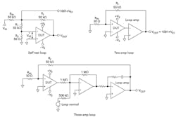
Testing for IQ might seem quite simple at first glance. This is especially true when testing very low or very high quiescent components. Designers can opt for one of three typical test circuits to test for IQ. Designers need to be aware of any load currents when performing IQ testing.
One area that engineers may overlook in doing this test is feedback current in the test loop. This is where the feedback resistor (RF) can load the part being tested, causing an error in the IQ measurements. The figure illustrates the three circuits that can be used to measure IQ.
Consequences of IQ
The IQ of a LDO regulator, used for regulation, plays a significant role in battery life. Battery life depends heavily on the load conditions while running, so LDOs with low IQ enable a simple solution to help boost the runtime of a battery-driven device.
These small devices aren’t just limited to consumer electronics. They also can play a big role in industrial applications like smart meters, building, and factory automation.
Even though designers may sometimes overlook quiescent current, it can eventually make a difference in the design by running a few seconds, days, or even years more.
Summary
This article provides the designer with some very basic, but important, tools in understanding quiescent current in their design architectures. The article also clarifies the distinction between IQ and shutdown current. Furthermore, it explains how to properly test for IQ and discusses the consequences of IQ in designs.
Check out more articles in the TechXchange: Why Low Iq is the Smart Thing to Do
References
LDO basics: Quiescent current, Texas Instruments
The Basics of Testing Operation Amplifiers: Three Methods
Quiescent Current vs Shutdown Current for Load Switch Power Consumption, Texas Instruments
LDO basics: introduction to quiescent current, Texas Instruments

