Automotive Smart Fuse Aids in Diagnosing Intermittent Shorts (Part 1)
Members can download this article in PDF format.
What you’ll learn:
- How the smart fuse itself works, as opposed to a regular fuse, in a car.
- Operation of the smart fuse’s power-on and bang-bang functionalities.
- How the smart fuse’s boot-up operation works.
From navigating the steep and winding roads of mountainous Big Sur, Calif., to wading the treacherous intersections of Cancun during a torrential downpour, my trusty 5-speed, manual-transmission, '94 BMW 325i has been through thick and thin. I love that car but must admit I’ve also had to endure an occasional, pesky, intermittent short circuit that blows a 7.5-A blade fuse.
When the fuse blows, the windows (motors are on separate 15-A fuses) don't work at all, so at a minimum, it's an inconvenience, and at maximum, could mean driving in very poor weather conditions or leaving the car parked with stuck open windows.
That the occurrence is intermittent makes it all the more annoying. It means I can only troubleshoot the problem when it’s present, a sometimes frequent and other times infrequent occurrence—and always of unknown duration. And every time it happens, I have to replace the blown fuse.
Automotive wiring diagrams are rather arcane. Nevertheless, I traced out part of the circuit controlled by that fuse. The harness goes from the primary fuse box under the hood directly back into the cabin and through the dashboard. Part of it then snakes down under the carpet to a module mounted beneath the driver's seat, where a vehicle tilt detection sensor is located. If the sensor determines that the vehicle is flipping over, it commands the windows to immediately close to prevent occupants from possibly exiting the vehicle.
Multiple other loads are on the harness where that 7.5-A fuse controls the applied voltage. It isn't practical to assume the short is not in the cabling; rather, that it’s in one of the many connected loads (modules) and they need to be disconnected one by one in a trial-and-error effort to find the culprit. Removing them makes the vehicle potentially not drivable and may severely compromise built-in security features.
What remains is to build a circuit that will replace the fuse and automatically:
- Connect the load when the short is absent.
- Disconnect it and provide an indication when a short is detected.
- Eliminate having to replace blown fuses.
- Present no appreciable safety compromise, fire hazard or otherwise.
That is at a minimum; later in this article I will mention another emergent, valuable consideration that makes this project worthwhile and interesting.
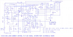
Before detailing the operation of this solution (Fig. 1), I'll mention that the first stab at this was MUCH simpler: The fuse was just replaced with a positive temperature coefficient (PTC) current interrupter. When current passing through the PTC is within prescribed limits, it represents a relatively low impedance. If the current goes out-of-bounds, though, its impedance rises drastically and limits that current flow.
Although this “solution” didn’t indicate when the short was present, it otherwise worked. Except it got way too hot, so hot that it partially melted the plastic of the adjacent blade fuses (but, nothing else) in the fuse box.
Smart Fuse
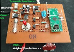
As shown in Figure 2, the Smart fuse replaces the regular (dumb) fuse in the fuse box. You can see that the corners of the plastic automotive blade fuse (shown leaning against the front of the breadboard) have been cut away to expose the upper blade edges of the original fuse (with the blown element) and that solder has been applied.
The circuit has three connected wires: RED (Vbatt), BLACK (Chassis GND - negative side of vehicle battery), and WHITE (to normally 7.5-A fused load). The RED solders to the side of the dumb fuse normally connected to +12 V dc in the fuse box, and the WHITE solders to the other side of the fuse going to the load. The BLACK wire must connect to any convenient chassis GND point that's available.
These connections are made with the vehicle off and the key in the OFF position; accessories are also OFF. The soldered fuse assembly is then inserted into its normal slot in the fuse box. The Smart fuse then takes the place of the now blown, regular 7.5-A fuse element.
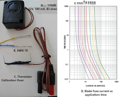
The actual wiring soldered from the fuse blades (and exiting the fuse box) to the Smart fuse connections is 18 Ga. Although most readers are familiar with this wire size, the stripped ends are shown in Figure 8 (see below) to illustrate the small diameter. Diameter size is significant because, as explained later, it's beneficial if the wiring is long enough to allow placing the Smart fuse in the passenger compartment instead of under the hood. The 18-gauge wire is rated 15-24 A, depending on insulation type and ambient temperature, so adding 1.5 to 2 meters (to and from, ~21 mΩ/meter) into the passenger cabin isn’t a problem.
High-Side Control
Now, as to the nature of the electronics, this fuse is a high-side control element, meaning it’s in series with the +12 V dc line and not the chassis GND line. The high-side current can be controlled with majority-hole-carrier transistors like bipolar PNP or enhancement-mode P-channel MOSFETs and a chassis GND-referred control circuit.
However, the PNP uses too much drive power (into the base) and has other problems. Moreover, P-channel FETs have relatively much higher channel resistance than their N-channel counterparts, are much fewer in number to select from, and are more expensive.
Perhaps the most important of those considerations in this application is the channel resistance, as it will be carrying amps of load current. If the RDS(on) is too high, this can mean heatsinking and, in some cases, even forced cooling (air or water).
To minimize or eliminate these issues, it’s best to use N-channel MOSFETs. A wide variety of them are available, including large-area devices with an almost fully enhanced channel at VGS ≤ 5 V. This availability means that today's “low” voltage logic-level devices can control these N-channel MOSFETs directly without any level translators.
Selecting N-channel FETs, however, means that a voltage source above the +12-V power rail is needed to provide the required gate-to-source voltage (VGS) to enhance the channel and turn on the transistors. While there are multiple ways to develop the high-side voltage source, the circuit in this application uses an inductor-based, bang-bang-type switching regulator. This power-supply presents some interesting functionality in itself; however, since the primary focus of Part 1 of this series is the load switching, the equations and explanation of design considerations will be left to Part 2.
This smart fuse is based on a bootstrapped microcontroller (MCU, designated “U1” in the schematic) running code that makes all pertinent decisions as to whether there’s an overload current on the fused line, whether to break the current, for how long, etc. I’ll explain more on this topic in a later section.
For now, to comprehend the high-side bang-bang, it's important to understand that the MCU contains internal analog and digital peripherals that form part of the switching power-supply.
Power-on and Bang-Bang Functionality
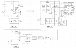
Figure 3 illustrates parts A, B, and C of the smart fuse’s power-on and bang-bang functionality. Part A shows the current flow path at turn-on when switch SW1 is first closed, and omits fuse F1 for clarity, considering it a short circuit (more on F1 later). In addition, all components not affecting the initial current flow path during turn-on also are removed from the part A schematic for clarity, including the MCU and transistors that are initially unpowered and off, etc.
Part A reveals that when SW1 closes, the battery current flows through L1 and D1 and charges capacitors C1 through C3. These charge as voltage dividers, and since C1 << (C2 + C3), it will charge to 5 * Vd = 3.5 V relatively quickly. Then, the parallel combination of C2, C3 will charge. Q6 turns on the series diode clamp circuit while C1 is charging to prevent overvoltage at AVDD and turns off the diode clamps when C1 is not charging.
R3 is a current-limiting resistor that prevents the diode string from having to support too large a current, forming a time constant with (C2 + C3) to determine their charge rate at turn-on. R2 is just a bleed resistor to “quickly” discharge (C2 + C3) at turn-off in case Q3 is off, and then re-enable bootstrapping if desired. It also sets the dc current flow from Vbatt to Chassis GND under steady-state operation at only ~12 V/10.82 K = 1.1 mA.
Once C1 is charged, MCU U1 will turn on as shown in part B of Figure 3 (part C is a simplified version of part B). The MCU boots up using an internal HFRCO oscillator and is immediately switched from 19 MHz to running at 38 MHz for the most efficient energy usage. Via PC0, the MCU turns on Q1, which has an RDS(on) ~= 40 mΩ (so, for this explanation we’ll consider it a short), and this is what affects the bootstrapping: The Q1 source is connected to a 20-mΩ current-sense resistor (five 0.1-Ω resistors in parallel) that, for now, we'll also consider a short.
So, when Q1 turns on, the MCU circuit common point (labeled by a filled-in GND symbol, while chassis GND is a hollow GND symbol) is directly connected to the battery +12-V terminal. The MCU, its power supply, and associated circuitry all ride on top of the battery voltage. They also make regular load dumps and other noise-type events on the positive-rail common-mode and essentially don't-cares for the analog functionality of the smart fuse.
A dedicated, hysteretic internal analog comparator that monitors the voltage across C1 (VMONAVDD, see part C) is enabled in the code. It's set with an upper threshold of 3.426 V dc and a lower threshold of 3.400 V dc as the power-supply voltage range to the MCU and IOVDD. It’s therefore also the GPIO logic-level Hi voltage range that directly drives the gates of the external power FETs, Q1 and Q3.
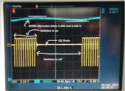
When the thresholds are hit, the VMONAVDD issues an interrupt to the CPU to either turn on or off TIMER0. When turned on, TIMER0 drives current-source Q5 and 500-mA transistor Q2 via PA0. When they’re on, D1 is reverse-biased, and −Vbatt charges L1. When TIMER0 turns them off, L1 forward-biases D1, dumping its energy into C1, and the short current return path is through RSense and Q1. The switching frequency is approximately 100 kHz as shown later in some screen captures.
Once the inductor is switching, the power supply can keep the MCU bootstrapped indefinitely as long as SW1 remains closed. Much more to come about this negative-to-positive step-down, burst-mode controller in Part 2 of this article.
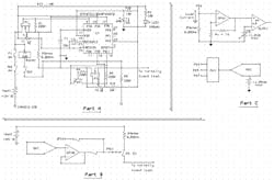
For now, let's concentrate on the critical, load-switching properties of this smart fuse. Figure 4 shows a simplified version of the schematic without power-supply components.
Smart-Fuse Load Switching
Immediately after the MCU is bootstrapped and the power supply is activated, the current flow path from Vbatt to the load is enabled. Refer to Figure 4 part A and the simplified version in part B.
This layout makes use of the internal op-amp buffered DAC; in the associated code, its output voltage on PB11 is linearly ramped from close to 0 to max output 4095. This voltage drives Q4, saturates it, and the op-amp output voltage is gradually applied to the Q3 gtate until reaching its maximum available value, strongly enhancing Q3’s channel. Q4 is required to isolate PB11 from voltages that are negative (and thus, impermissible) with respect to MCU GND whenever Q3 is off.
At this point, PB11 is switched to logic-level GPIO Hi output and the DAC/op-amp is disabled to reduce AVDD load current internal to the MCU. This setting allows for a longer time between power-supply C1 charging periods.
Current to the normally fused load then flows from Vbatt → SW1 → F1 → Q1 → RSense → Q3 and out the fuse box to the load. The DAC allows for a gradual reapplication of fused load current amplitude on connection retries via Q3 VGS tailoring after an overload is detected, instead of just a hard and fast full load-current application. This application uses a simple ramp function to turn on Q3, but it can be any waveform generated by the DAC.
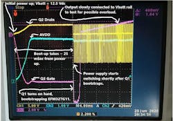
The overload detection shown in Figure 4, part C is affected by measuring the current through the 20-mΩ RSense at PD6 and amplifying it via an internal op-amp configured in a non-inverting gain of 16. Then it’s fed to an internal analog voltage comparator (ACMP) with an adjustable threshold voltage. Again, refer to Figure 4, top of part C. For this circuit, that threshold is 6 A. It’s important to understand how that value is determined. But first, see Figs. 5-7 showing detailed oscilloscope shots of the overall Smart fuse performance.
Smart-Fuse Boot-Up Operation
The critical performance features of the smart fuse are best detailed at boot-up because the full functionality of the circuit depends on accurate bootstrapping action and initiation of the power-supply switching action. If boot-up takes place too long after power application, C1 voltage (AVDD) will sag far enough whereby U1 GPIO output Hi will not sufficiently enhance the Q1 channel for bootstrapping and the Q2 channel for charging the inductor.
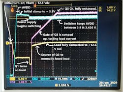
All signals in Figure 5 relate to MCU GND; Vbatt = 12.5 V dc:
At turn-on, AVDD (BLUE) quickly ramps to ~3.6 V, as determined by the diode string and Q6. It’s important to avoid overshoot here, as the max allowable voltage for the MCU is 3.8 V.
- The Q3 source (YELLOW), which is connected to Chassis GND via R8, adopts −Vbatt minus the AVDD charging voltage path including D1, and stays there for the MCU boot period of ~ 23 ms. Then, the bootstrapping, shown as the yellow trace, rapidly descends to –Vbatt as Q1 turns on hard.
- Immediately after bootstrapping, the power supply is enabled and switching action occurs, as shown in the blue trace where AVDD sags to 3.4 V and then is charged back up to 3.426 by L1.
- At ~ 25 ms, the DAC output ramp is applied to the Q3 Gate (RED). Before this application, the Q3 gate has the same voltage as the Q3 source (YELLOW) because Q3 is off and no current flows through R5. However, as soon as Q3 begins to conduct, these voltages separate. As shown at the end of the ramp, the gate voltage is ~3.4 V dc (nearly the same as AVDD), but the source is at MCU GND, as desired, to connect Vbatt to the fused load. Also note that the Q3 source reaches MCU GND = Vbatt at VGS ~= 2.4 V, the threshold turn-on voltage for Q3 at room temperature.
Note in Figure 7 the clean and fast switching action of the Q2 drain between –Vbatt and AVDD + Vd (Schottky) and the tight regulation of AVDD between 3.400 V and 3.426 V with little or no overshoots or undershoots.
Overcurrent Limit
The 6-A threshold overcurrent-limit setting is determined by several factors. Foremost, the dumb fuse that’s being replaced is rated at 7.5 A, so the threshold must be lower than that. The next lower commercial fuse magnitude is 5 A, so the threshold must be greater than that.
Viewing the Littelfuse current vs. time for these automotive blade fuse types in Figure 8, part D, it’s apparent that these fuses will tolerate more than the rated current for some limited time. However, that’s likely to involve inelastic deformation of the fuse element and therefore degradation of the long-term rating. I suspect BMW design engineers select these fuses based on the absolute peak current normally expected during operation, i.e., operation on the left of any given curve and at the top of the chart, which in this case, would always mean < 7.5 A.
Up Next
In Part 2 of this series, we’ll:
- Continue the explanation of how the fused current pass transistors are selected and monitored via thermistors, as well as the code algorithm to safely control the load current.
- See what extended protection features are included in the Smart fuse beyond the semiconductor current flow path protection.
- Explain in detail the equations and engineering considerations behind the negative-to-positive, step-down bang-bang controller.
- Learn how the smart fuse incorporates all required components of a formal data-acquisition system that enables understanding the electrical current usage profile for the fused load that’s been causing pesky, intermittent shorts in my BMW. Perhaps the nature of the current flow will clue us in as to where, exactly, the fault may lie…information we can glean from the Smart fuse even when the intermittent short is NOT present.

