Creative Ways to Tame EMI
This article is part of the TechXchange: Delving into EMI, EMC and Noise
Members can download this article in PDF format.
What you'll learn:
- How does direct-spray EMI coating work?
- EMI filters for motor drives.
- Looking at SiC multiplexing converters for EMI in EVs.
- Magnetically integrating single- and multi-stage EMI filters.
Circuit designers want to design the best kinds of circuits with optimum performance. Those designers usually dread having to add a pesky electromagnetic-interference (EMI) filtering circuit to their nice, neat, and creative design. In this article, we will demonstrate some relatively simple EMI blocking circuitry to ease a designer’s pain.
EMI Shield Coating for Individual Package-Level Components
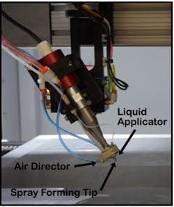
In today’s modern, tight packaging of electronic circuitry, creativity is becoming necessary to ensure EMI shielding. How do we minimize the weight, thicknesses, and cost of shielding in our circuit design? Enter direct-spray EMI coating processes. For instance, there’s a direct-spray process known as Ultra-Thin Coating Application Technology or t-CAT.1
t-CAT is able to easily spray a wide variety of materials, including pure solutions, suspensions, and slurries, which will produce a uniform coating layer on the substrate. It also can apply “conformal” layers to surfaces with 3D microstructures (Fig. 1).
Active EMI Suppression in Motor-Drive Systems
Motor-drive systems generate EMI when their switching power transistor devices are actively switching. Since EMI might induce a fault operation of the protection circuit and thus must be suppressed, EMI filters are usually added in the main circuit.
Two kinds of EMI common filters exist:
- Passive EMI filter: These filters typically use inductors and capacitors to attenuate the EMI.
- Active EMI filter (AEF): AEF designs employ transistors and operational amplifiers (op amps) designed to inject the compensation voltage or current into the circuit to attenuate the EMI.
Designers may want to use an active EMI filter to reduce the dc side common-mode (CM) EMI in motor-drive systems.2 This method is far different from the traditional passive EMI filter that’s traditionally added in the main circuit.
This active EMI Filter (AEF) is added in the grounding circuit that’s connected between the motor frame and the ground. The architecture can be decoupled from the main circuit. By optimally setting the components values, the dc side CM EMI will be suppressed while retaining a low motor-frame voltage.
The AEF structure is relatively simple, and the volume of the AEF can be made quite small. Experiment results have shown that the effects of the proposed AEF have been verified and it was able to suppress the dc side CM EMI in the motor-drive system, while maintaining a low motor-frame voltage.
Investigating EMI in a SiC-Based Multiplexing Converter for EVs/PHEVs
Designers need to investigate conducted EMI characteristics of an on-board multiplexing converter that uses paralleled silicon-carbide (SiC) devices to reach high efficiency and high power density for applications in electric vehicles (EVs) and plug-in hybrid electric vehicles (PHEVs).
This design looks at integrating the on-board charger (OBC) and the electric drive system of an EV/PHEV while maintaining a low EMI signature. SiC devices have high-performance capabilities over MOSFETs and other power elements. A SiC power converter offers faster switching speeds (di/dt, dv/dt) along with high switching frequency capability. One drawback of SiC power switching, though, is significantly increased EMI in the power converter.
Designers need to investigate EMI suppression methods of the multiplexing converter to keep emitted noise below accepted EMI standards.3 Some possible solutions include:
- In the dc-dc working mode, the series resonance between the high-frequency transmission-line effects of the input power inductor and the input negative lead parasitic inductance will increase the conducted EMI levels within a particular frequency band. This input negative lead parasitic inductance can be reduced by adding a small, packaged X capacitor, which will eliminate the CM EMI resonant spikes in a specific frequency band.
- The Equivalent Parallel Capacitance (EPC) of the input power inductor can be reduced by optimizing its method of winding. This will help to improve its high-frequency impedance characteristics, reduce the high-frequency oscillation amplitudes of the inductor currents, and significantly reduce the system EMI levels. The winding method of the input power inductor is optimized to improve its high-frequency impedance characteristics and by adding a small, packaged X capacitor that will help to reduce the parasitic inductance of the input negative lead. The conducted EMI test results of the multiplexing converter, in the dc-dc working mode, will now meet the GB/T 18655-2018 level 1 peak limits.
- In the non-isolated OBC working mode—when compared to the isolated OBC—the output shielded cable will increase the CM EMI levels in the low-frequency ranges (less than 350 kHz) and in the mid-frequency ranges (6 ∼ 8 MHz). The OBC conducted EMI characteristics will depend mainly on the front-stage ac-dc converter. This EMI will be minimized, in the frequency ranges from 1 to 30 MHz, via optimization of the winding method for the input power inductors. The conducted EMI test results of the multiplexing converter in the OBC working mode will meet the quasi-peak limits of CISPR 32-2019 with the addition of grid side EMI filters, which will be installed together with the input power inductors. There’s no effect on the system power density.
Magnetic Integration of Single-Stage and Multi-Stage EMI Filters
Power-density requirements are increased in a grid-connected voltage source inverter (VSI) by increasing the inverter’s switching frequency to reduce the size of passive components. When doing this, EMI will worsen and must be reduced.
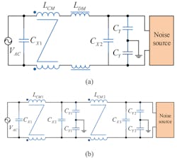
Traditionally, EMI filters have many discrete elements that can occupy 15% to 20% of the entire converter volume. Discrete inductors are typically the biggest offenders. A few integration methods have been proposed to reduce the volume and weight of passive EMI filters with higher power density. There are two typical solutions: integrated passive filters with a planar printed circuit board (PCB) and integrated inductors with a single core unit.
Figure 2 shows an integrated single-stage passive EMI filter (ISSEF) as well as a multi-stage passive EMI filter (IMSEF).
Read more articles in the TechXchange: Delving into EMI, EMC and Noise
References
1. “Application of package-level high-performance EMI shield material with a novel nozzle-less spray coating technology,” USI Ultrasonic Systems, 2020 IEEE 70th Electronic Components and Technology Conference (ECTC).
2. “An Active EMI Filter in Grounding Circuit for DC Side CM EMI Suppression in Motor Drive System,” IEEE Transactions on Power Electronics, Vol. 37, No. 3, March 2022.
3. “Conducted EMI Investigation of a SiC-Based Multiplexing Converter for EV/PHEV,” National Key Research and Development Program of China
4. “Magnetic Integration of EMI filter for Grid-Connected Voltage-Source Inverters,” 10th International Conference on Power Electronics—ECCE Asia, May 27 to 30, 2019, BEXCO, Busan, Korea


