Hardware Design Guide to Smartphone Ambient-Light Sensing
This file type includes high-resolution graphics and schematics when applicable.
Since the backlight of the LCD panel in a smartphone accounts for around 40% of the device’s total power consumption, one can benefit greatly by adjusting the brightness in response to changes in ambient-light levels. In a relatively dark environment, the brightness of the display can be reduced to save power. This is also easier on the user’s eyes, thus improving the user experience at the same time.
Ambient-light sensors (ALSs) are in fact now widely used in smartphones to provide information about ambient light levels, in support of the backlight LED power circuit. But while this application is simple to describe, in practice it’s difficult to implement successfully—i.e., in a way that achieves worthwhile power savings while remaining unobtrusive to the user.
An ALS must be mounted behind a display screen in which every square millimeter of area is valuable. In addition, it must be able to perform proximity detection (to turn the display off when held to the user’s face) as well as the core ambient-light measurement function. These and other constraints seriously limit the design engineer’s freedom to optimize the design.
This article describes the main challenges in implementing successful ambient-light response in a smartphone. It also offers ways to overcome these challenges to achieve highly responsive and accurate adjustment of the backlight’s brightness in response to ambient light.
Photopic Response
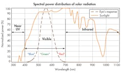
The first difficulty is that photodiodes respond differently to light than the human eye. The human eye is insensitive to infrared (IR) light (a wavelength greater than 780 nm) and ultraviolet (UV) light (a wavelength less than 380 nm). A standard silicon photodiode, on the other hand, normally senses light at any wavelength between 300 and 1100 nm.
This means that the designer’s first challenge is to remove the IR and UV components from the sensor’s output. The function of the ALS is to capture a measurement of the illuminance (of which the unit of measurement is the lux) incident on the display of the smartphone. If this lux measurement includes UV and IR as well as visible light, the display’s backlight controller will receive a distorted representation of the human, or “photopic,” response to ambient-light conditions. In short, the ambient light will tend to appear brighter to the sensor than to the human eye.
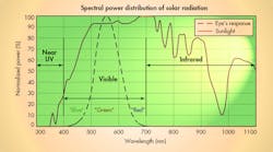
This is because both natural and artificial light contain an IR element. This is true, for example, of both sunlight (Fig. 1) and the light from an incandescent lamp. An obvious way to remove the IR light is to overlay an optical IR filter on the sensor. But in a smartphone, this same sensor is also typically used for proximity detection (in tandem with an IR LED) to turn off the display and touch controller while the phone is held to the user’s face.
Of course, the smartphone designer could then add a separate IR photodiode just for proximity sensing. However, this is an inelegant solution—now the design must carry the cost of the optical filter on the ALS as well as a discrete IR photodiode. Moreover, additional space will be occupied by the IR photodiode, which requires an aperture in the face of the display to allow for the passage of IR light.
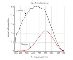
A more streamlined solution to the problem is a dual-diode module, which has been developed by ams. One photodiode (shown as Channel 0 in Figure 2) senses the full spectrum, while the other (shown as Channel 1) senses light mainly in the IR portion of the spectrum. Subtracting the IR photodiode’s output from the full-spectrum sensor’s output produces a measurement of visible light.
The sensor is fairly insensitive to UV light, and in any case, the common light sources emit little UV radiation. In most cases, a packaging material that can absorb UV light is sufficient to remove it for the purpose of ambient-light sensing.
Having removed the IR component of light from the ALS’s output, the smartphone designer now has a second problem to solve: How do you limit the angle of view of the ALS/proximity-sensor module without impairing its performance? This is a matter of trading off the ALS against the proximity sensor.
For ambient-light sensing, the ideal angle of view is a (practically impossible) 180°, since this is the angle of view of the display on which ambient light is incident. But for proximity sensing, the opposite applies—a narrow viewing angle is required in order to limit the potential for crosstalk between the IR LED and the IR sensor. Ideally, the IR sensor should only be able to sense IR light reflected from the user’s face, and the LED should not be able to illuminate the sensor directly, or to reflect light from the top or bottom surface of the touch panel.
This conflict between the requirements of the ALS and the IR sensor therefore requires a tradeoff. Through experimentation, smartphone designers have found that a 90° to 110° viewing angle provides for high-performance proximity detection while still enabling relatively good performance in the ambient-light sensing system. Narrowing the angle below 90° dramatically impairs the performance of the ALS. In addition, for the system to work with a 90° viewing angle, a very small air gap must exist between the bottom of the touchscreen and the top of the sensor module.
The viewing angle is not the only question of mechanical design that affects the ALS. For light to pass through the screen to the sensor module, the designer must leave an aperture open. OEMs want this hole to be as small as possible, though, to avoid spoiling the sleek, smooth appearance of the touchscreen. They also mask the aperture’s appearance with ink added to the screen’s glass surface, which darkens it and blends its color with that of the phone’s case. The ink and the small aperture both reduce the intensity of light incident on the sensor module.
In addition, on the production line, the OEM must strictly control the variation in the ink’s transmissiveness. If, for example, a 17% transmissive ink is used, a variation of just ±1% in the transmissiveness of the ink will cause a 5.9% additional error (1/17 × 100) in the ALS’s output.
The third important design challenge in implementing ambient light sensing in a smartphone is to handle a very high dynamic range of light inputs. Smartphone manufacturers want the display backlight’s brightness to be set appropriately whether the device is being used in almost total darkness (illuminance as low as 0.1 lux) or in direct sunlight (illuminance as high as 220 klux). This requires that the sensor offer high sensitivity over a very wide dynamic range while maintaining a very low noise floor. In addition, the device’s gain should be controllable in response to changes in the brightness of the ambient light.
Fine-Tuning the Implementation
This article has described the tradeoffs that govern the implementation of ambient-light sensing in smartphones, the advantages of a dual-diode solution, and the characteristics of the ALS module that the OEM needs to specify. But every device’s appearance, mechanical design, and ink are different, which calls for individual characterization in order to develop a customized lux equation. This equation is required to accurately remove the IR component of ambient light, and to compensate for the restricted angle of view.
To perform this characterization, the smartphone should be exposed to various types of light sources that emit varying proportions of IR and UV light. The lux measurements of a reference, ultra-accurate lux meter and the ALS module under the same lighting conditions are then compared in order to calibrate the module’s output. The lux meter should be covered by a hood so that it mimics the light sensor’s restricted angle of view.
To characterize a sensor module such as the ams TMD27721 or TMD27723, for example, the following equations would be used:
CPL = (ATIME_ms × AGAINx) / 20
Lux1 = (C0DATA – a0 × C1DATA) / CPL
Lux2 = (b0 × C0DATA – b1 × C1DATA) / CPL
Lux = MAX(Lux1, Lux2, 0)
where CPL, a0, b0, and b1 are the parameters to be characterized. CPL = counts per lux; C0DATA = data read from Channel 0; C1DATA = data read from Channel 1; C0DATA – a0 × C1DATA = weighted count for a light source with a high proportion of IR lightb0x; C0DATA – b1 × C1DATA = weighted count for a light source with a low proportion of IR light; and MAX = maximum value of Lux1, Lux2, and 0.
In general, the more data sets that are collected under more light sources, the more accurate the characterization.
Given an appropriate mechanical design, strict control of ink transmissiveness in production, and careful characterization, error in the ambient-light sensing system can be limited to no more than ±15%. In some cases, it’s possible to achieve as little as ±10% error. This is good enough to serve the purpose of adjusting the backlight’s brightness to save power and improve the user’s experience.
Of course, an OEM might require much higher accuracy for a function other than display backlight control. This would call for a very high-sensitivity ambient-light sensor (as a standalone device with no proximity detection). One such example is ams’s TSL25911.
Summary
Ambient-light sensors (ALS) are widely used in smartphones to provide information about ambient-light levels, in support of the backlight LED power circuit. But while this application may be simple to describe, in practice it’s difficult to implement successfully—i.e., in a way that achieves worthwhile power savings while remaining unobtrusive to the user.
An ALS must be mounted behind a display screen in which every square millimeter of area is valuable. It also must be able to perform proximity detection (to turn the display off when held to the user’s face) as well as the core ambient-light measurement function. These and other constraints severely limit the design engineer’s freedom to optimize the design.
The overcome the main challenges in implementing successful ambient-light response in a smartphone, designers must:
• Remove the IR component from the light measured by the ALS.
• Overcome limitations in the viewing angle that’s exposed to the ALS.
• Provide accurate measurements of ambient light over a very wide dynamic range.
Looking for parts? Go to SourceESB.


