Measuring DCIR of Lithium-Ion Cells
While ac internal resistance (ACIR) measurements are quite common and somewhat standardized when measuring lithium-ion cells, dc internal resistance (DCIR) measurements are nonstandard and generally misunderstood. DCIR is also sometimes interchangeably called pulse testing, which can lead to further confusion.
First, let’s take a quick look at ACIR. To measure ACIR, an ac signal, typically an ac current (Iac) is passed through the cell and the voltage response (Vac) of the cell is measured. The ac current is usually around 100 mA and the frequency is 1000 Hz. The impedance at 1000 Hz is calculated as Vac/Iac. There can be phase shift between the Iac and Vac as we measure impedance. So, to keep it simple, the real part of the impedance Vac/Iac is called the ACIR.
It’s unlikely that any real-world application of the cell will present a 1000-Hz sinusoidal current load on the cell. Therefore, this measurement of ACIR doesn’t reveal much about how the cell will behave in a real-world application. However, ACIR has become a very standard way of assessing the cell’s resistance.
DCIR, on the other hand, has no such standardization.
DC Resistance Measurement
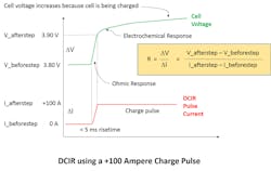
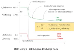
DCIR looks to measure the dc resistance characteristic of the cell. As with ACIR, to measure resistance, you apply a change in current and measure the voltage response. In this case, because it’s DCIR, we’re making a true dc resistance measurement—there’s no impedance and no ac signal generation. Instead, a step change or pulse is used: DCIR = (V_beforestep – V_afterstep) / (I_beforestep – I_afterstep).
Normally, the first measurement (before step) is made when the cell is at rest, so V_beforestep = cell open circuit voltage (OCV) and I_beforestep = 0 amperes. The applied step change in current can be a step up in current, which is a charge pulse, or it can be a step down in current, which is a discharge pulse. In fact, you may want to measure the DCIR in both directions and compare or average the results.
As to the size of the step of current, this is normally a large current step because the very low resistance of the cell will need a large current step to create a measurable response in voltage. I’ve seen requests for current steps as high at 20 C. For a 50-Ah cell, that’s 1000 A, so DCIR equipment can be large and expensive. With high currents, you can’t leave the high current to be applied indefinitely or the cell will heat up and charge (if the current pulse is positive) or discharge (if the current pulse is negative). In either case, it isn’t desirable to change the state of charge (SoC) of the cell, so the current is usually applied as a short pulse.
Now, if we’re applying a pulse to the cell, how wide should the pulse be? Also, if we’re measuring V_afterstep, when is the right time to make the measurement? It’s immediately after applying the pulse or toward the end of the pulse before the cell is returned to its “before step” state (which is typically resting state, as mentioned above).
Digging into DCIR
To answer that question, let’s look at the meaning of DCIR. DCIR measures the ohmic series dc output resistance of the cell. The cell’s ohmic resistance comes from the current collectors, the active materials of the electrodes, the ionic conductivity of the electrolyte, and other connections (like tab welds, contact resistances, and safety elements).
Electrochemical reactions and other phenomenon aren’t part of the ohmic resistance. These will each happen at different rates, and therefore aren’t dc, and will instead contribute to the ac impedance of the cell. Thus, ACIR will measure those effects that happen at around 1000 Hz. However, a full electrochemical impedance spectrum measurement using an EIS instrument will be needed to see the full effects of these electrochemical phenomenon that occur at different rates.
For DCIR, we only care about the non-time varying DC ohmic resistances. The voltage change due to these ohmic resistances will appear instantaneously upon application of the current pulse and thus to measure DC ohmic resistances, you must immediately measure the voltage response upon application of the current pulse. This means the length of the pulse does not matter and the pulse need not be any longer than the measurement time of the cell’s voltage response. In fact, you want that pulse to be as short as possible to avoid self-heating and to avoid any un-necessary change in SoC caused by the charging or discharging of the cell during the pulse.
In discussions with engineers and scientists about DCIR, I’m often requested for DCIR pulses that are 1 second or 10 seconds or 30 seconds wide, as well as to make the measurement of the cell’s voltage response V_afterstep at the end of this pulse. This is not a DCIR measurement, but instead is a dc pulse measurement.
If measured at the end of the pulse, V_afterstep will certainly include the effects of the dc ohmic resistance, but V_afterstep will include some ac electrochemical effects and most significantly will include a change in voltage due to charging or discharging the cell during the pulse. As the pulse length becomes longer and the pulse amplitude gets larger (remember, this test could be run at 20 C), this charging or discharging effect on OCV can be quite large compared to the very small voltage change caused by a 20 C current flowing through a few milliohms of true cell ohmic resistance.
That’s not to say pulse measurement isn’t valid. In fact, a pulse measurement will most certainly give valuable cell behavioral information, as a short pulsed load on the cell is a common real-world signal. Think about how stepping on the accelerator would present a pulsed current to an electric-vehicle (EV) battery, or how a GSM transmit burst presents a pulsed load to a mobile phone battery. My point, though, is that a dc pulse test and a DCIR measurement measure two different characteristics of the cell. And while both measurements are done with a large current pulse, making each measurement is different.
Test Setup
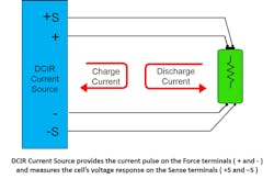
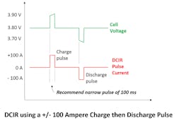
Figures 1 and 2 show the test setup to measure DCIR and the expected voltage and current waveforms.
Measuring DCIR using the test setup in Figure 1 requires two instrumentation characteristics:
- The device that’s applying the current pulse needs a risetime of a few milliseconds or faster. If the edge is slow, the time it takes to make the transition from I_beforestep to I_afterstep will allow for non-dc, fast electrochemical effects to occur, such that the measurement of the voltage response will include both dc ohmic and some ac electrochemical voltage components.
- The measurement of the voltage response V_afterstep must be fast and made immediately upon completion of the applied current step. If the measurement is slow or delayed, the V_afterstep will include for non-dc, fast electrochemical effects. Taken to the extreme, if the V_afterstep is measured much after the transition, the DCIR measurement becomes a dc pulse measurement.
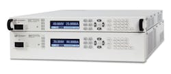
Testing currents up to +100 A charging pulse or −100 A discharging pulse can effectively be performed with an instrument like the Keysight Advanced Power System (Fig. 3). It can be configured to provide positive or negative current pulses with millisecond risetimes using its transient pulse mode. It also has high-accuracy, independent voltage and current digitization with 18-bit ADCs that enable direct measurement of DCIR in a single instrument. For pulsed currents over ±100 A, the Keysight RPS family offers the same capabilities at higher current levels.
Using the Keysight APS, we tested a 26-Ah pouch cell and found its DCIR to be 1.3 mΩ. Comparing results for a charge pulse of 100 A to a discharge pulse of −100 A, we saw a difference of 3 µΩ from a charging pulse to a discharging pulse.
We also investigated repeatability and noise of the DCIR measurements and found standard deviations of < 1 µΩ for the pouch cell at ±100 A. When considering repeatability, the connection to the cell is a key factor. We measured approximately 20-µΩ variability in this connection, but this will depend greatly on the type of fixture or connection to the cell. A 4-wire connection to the cell as shown in Figure 1, available with the Keysight APS and RPS, minimizes this variability.
Lastly, I’d like to thank my colleague Bryan Boswell, Senior Design Engineer at Keysight Technologies, who set up and performed these measurements, and did extensive work on how to analyze the results to make a practical DCIR measurement using off-the-shelf high-current instrumentation.
