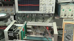
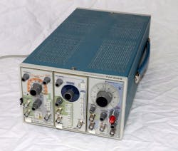
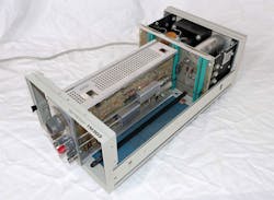
A former coworker friend sent me a Tektronix 3-slot mainframe and several plug-in modules (Fig. 1). The TM500-series mainframes are 1970s vintage, but like a lot of old test equipment, can still work well. Tek made the mainframes in 2-, 3-, and 6-slot versions. The 3-slot mainframe has a linear power supply in the rear, and a nifty black plastic pull switch on the front left edge to turn on ac power.
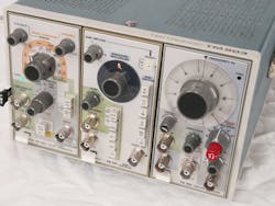
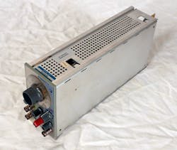
Some of the modules my pal sent over were a PG502 pulse generator, an RG501 ramp generator, and a FG502 function generator (Fig. 2). The ramp and pulse generator, as well as the 3-slot mainframe, seemed to work fine. The function generator was dead, and I needed it to test the bandwidth of a pair of differential scope probes that engineer extraordinaire Alan Martin sent me a few months ago. I have great friends—they keep sending me valuable test equipment.
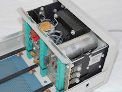
The 3-slot TM503 mainframe has a linear power supply with a hefty transformer and large electrolytic capacitors (Fig. 3). Alan Martin warned me, “TM503 3-slot frames are notorious for having one of the big aluminum electrolytic capacitors fail. Each of the TM500 frame sizes have certain unique quirks. TM506s can also benefit from a better fan. $17 at Digi-Key. Two of the TM500 mainframe manuals have schematic errors. Unusual for Tek.”
Engineer-Friendly Design
You can tell this old Tek test equipment was designed by engineers who also built and fixed their own electronics. The FG502 function generator plug-in pulls out for easy service (Fig. 4). The side panels pop open so you can get to both sides of the printed circuit board (PCB). There’s an extender card to let you work in the modules sticking out of the mainframe, but I just took the cover off the mainframe so that I could probe the PCB while under power. Be careful of the lethal voltages in the power supply of the mainframe.
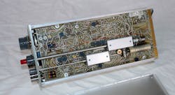
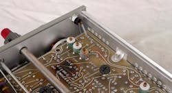
The solder side of the FG502 function generator has several adjustment potentiometers (Fig. 5). The manual is very thorough, like most Tektronix manuals. You can download the manuals from several sites online. Some of the PDF files have the schematics shrunken to one page; others have scanned the B-sized drawings on two separate A-sized pages. While harder to read on the computer, it allowed me to print the two pages out and tape them together to get a more readable B-sized schematic and assembly drawing.
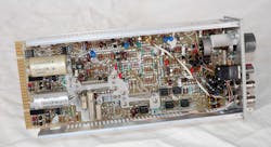
The component side of the FG502 function generator has a handful of LM741 operational amplifiers, thankfully installed in sockets (Fig. 6). Unlike later test equipment, there are no custom hybrid circuits or other proprietary parts, so you can usually fix this old stuff. The only downside is that the older equipment is larger than the new stuff. Still, this three-slot mainframe will be a nice addition to the “sources” side of my home lab.
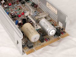
Also, there are several large electrolytic capacitors that tend to dry out and fail (Fig. 7). Texas Instruments application engineer Paul Grohe told me, “Replace C602 and the rest of the big trash-can filter caps, particularly if they are in a warm area. This unit is ‘vintage’ enough that they will start drying out. Check the ripple under load. The bigger the cap, the better they can hide their aging when lightly loaded. Tek was pretty good about using tantalum capacitors sprinkled about in the circuit, but the main filter caps are electrolytic.”
Note that the tantalum capacitors are also failure-prone. Analog guru Jim Williams told me that it was great that Tek used those “lemon drop” tantalum capacitors, since it meant you could buy broken Tek equipment cheap and fix them easily.
The power pilot light is an incandescent grain-of-wheat bulb (Fig. 8). When the FG502 module looked dead, I tried it on all three slots of the mainframe, as well as the 2-slot mainframe I own. I also verified that the outputs were dead—it might have been a burnt-out lamp. Grohe noted, “You can replace the pilot lamps with LEDs—blue ones if you want to get fancy. The bulbs are mounted in the little slip-in ‘caps’ and easily fit a little 3mm LED.”
Plug-In Play
I took the cover off the TM503 mainframe so that I could test the plug-in while under power (Fig, 9). It’s not too hard to get to both sides of the PCB when the plug-in is in the center slot, but you can move it to the outside slots to give more clearance to either side of the PCB.
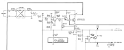
The dc power for the FG502 plug-in starts with a +20-V power supply (Fig. 10). That power gets dropped down to make a +17-V supply. The +20-V supply is also used to bias the op amps in the −20-V supply as well as its derived −17-V supply. Since all four supplies were dead, I started troubleshooting the +20-V supply. By simply swapping the LM741 op amp with one in the signal path, I got the power supply section fixed. The generator does not work yet, but I need to get a replacement op amp before I troubleshoot it.
The schematic of the +20-V supply initially confused me. It looked like Tek engineers were counting on only one polarity of the offset voltage of the LM741 amplifier to get the power supply to start. They bootstrapped the Zener diode off the supply, which would make less ripple than if they powered it off the raw dc voltage from the diode bridge.
I wrote several pals, and Paul Grohe pointed out, “My guess is that since the LM741 is not a rail-to-rail output, it will always be at least a volt or more from either rail when saturated, that may be enough to get the juice flowing in the Darlington transistor base-emitter junctions to start up the regulator. It may have problems if a ‘modern’ rail-to-rail op-amp is used. Tek is also pushing the common-mode limit on U635 in the 17V section. Plus, there is no output current limit resistor on the amp.”
Grohe, who is Bob Pease’s handpicked protege, also noted, “The switches are the PCB mounted ‘leaf and tumbler’ types, not the wafer deck types, so don't use any contact cleaners that leave a residue. It will soak into the PCB. The scope manuals have the cleaning procedure, and it's messy. If you use isopropyl alcohol, you have got to be sure you get it all out or else you will get the white residue on the next humid day.
“If you get bold enough, you can remove the tumbler to access the leafs. I just run a slip of paper under each leaf while lightly pressing down on the leaf. They are gold plated and in a nice, straight row, so you just need to get the dust, haze, and nicotine residue off. Usually you can remove the shields without affecting the switches. Always pull the paper away from the rivets, otherwise they could bend backwards, and that is ‘A Bad Thing.’ Be careful not to snag the leaf ‘fingers’ when first inserting the paper. Once that is all done, they will be good for another 40 years.
“Usually you can cure bad contacts just by exercising the knob, while disabling the detent ball by lifting up on the spring, to minimize the stresses to the shaft. My 501 sometimes will go ‘dead’ until I exercise the range and function switches a few times, while making sure it is not in the ‘hold’ position. The clue is that the offset control still works. Also make sure the phase knob is pushed in. And wiggle any of the transistors that are in the little individual spring-leaf PCB sockets. Geez, those are annoying. Commonly, the output devices are blown in these generators. As you know, generators are subjected to a lot of abuse.” The abuse might explain the burnt section of the PCB I noted in Figure 8. I will check the resistor values and resolder them if they are OK.
Troubleshooting the Signal Path
Grohe went on to give a nice overview of how to troubleshoot the signal path. “Set up the front panel as specified in the beginning of the calibration procedure, to make sure you have not overlooked one of the control settings. Turn the amplitude to ‘MIN’ and pull out and rotate the ‘Offset’ knob. If the output swings ±5 V, or ±2.5 V into 50 Ω, symmetrically around the mid-point, then the output stage is probably okay. Don't forget to turn the amplitude back up.
“Make sure the ‘CAL’ knob is all the way into the ‘CAL’ position. As I recall, it holds or stalls when fully cranked the other way, which may make it look dead. Check for a signal coming from the ‘TRIG OUT’ output.
“Another hint, if you are focusing on a particular part of the schematic, you can print out just that section and ‘blow it up.’ In Acrobat, zoom into that section to fill the screen with what you want, then hit print. In the ‘Pages to Print’ section, there is an obscure ‘More Options’ menu triangle; click it and then click ‘Current View.’ Then select ‘Fit’ in the ‘Page Size’ section. Then set the ‘Portrait/Landscape’ to what works best, usually landscape, and click ‘OK’ to print. I like to print to 11x17 so that I can make notes and voltage maps/traces. It's a lot easier on the eyes than trying to squint to read values or pin numbers.”
All good tips, although I use FoxIt reader for my PDF files; it’s pretty easy to select things to print. I also have been known to just do a screen capture of the schematic, and paste that into my IrfanView image program, and that makes it easy to crop and print out exactly what I want. I sold my B-sized Bother printer/scanner when I moved to Florida, but projects like this make me want to buy it again.
