How Mixed HW/SW Simulation Makes EVs Smarter, Tougher, and Greener
Electric and plug-in hybrid-electric vehicles (EVs and PHEVs) are helping the world end its dependence on fossil fuels while reducing the cost of transportation for their owners. But designing drivetrains for electric vehicles EVs/PHEVs is more challenging than conventional vehicles due, in good part, to the large number of electromechanical components involved and the complex interactions that occur between them. As a result, hardware-in-the-loop (HIL) simulation and testing has become one of the automotive industry's most important tools for navigating this increasingly complex design space.
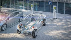
HIL testing that incorporates battery emulation can provide a competitive advantage for testing electric-vehicle components and systems. Battery emulation helps accelerate testing of the electric powertrain, dc fast charging, and other EV applications that require a battery for testing. (Credit: NH Research, https://nhresearch.com/testing-electric-vehicles-with-battery-emulation/)
Since HIL also plays a major role in the creation of many other products with complex electromechanical systems (agricultural equipment , utility-scale wind turbines, etc...), Electronic Design invited Joel Van Sickel, a Senior Application Engineer at MathWorks, to introduce some of the important concepts that underlie HIL testing. He also reveals some of the advantages HIL testing brings to the development of EVs/PHEVs and other energy-efficient products that will enable the transition to a vibrant, sustainable economy.
When you refer to HIL simulation, is this simulation of the ECU (I think that’s correct?), the hardware being controlled by the ECU, or something else entirely?
Good question. When discussing HIL testing, it is the hardware/system being controlled by the engine control unit (ECU) that’s simulated.
So "ECU" is the correct term for the controller that’s being tested. ECU is the common terminology in the automotive industry; otherwise, it would be referred to just as a controller or embedded system, often implemented on a microcontroller. But several other related types of mixed hardware/software testing are used for design and development that may or may not involve an ECU.
Before we dive into the technology, let's get familiar with some of the more common nomenclature used across industries:
Specific terms (these terms always communicate a specific implementation of a real-time system)
- CHIL simulation (controller hardware-in-the-loop): This is also typically what people mean when they refer to HIL. In this scenario, there’s real control hardware, such as an ECU connected to a real-time computer, which simulates the hardware being controlled.
- PHIL simulation (power hardware-in-the-loop): In this regime, the controller AND some portion of the power-handling hardware are being tested, with the rest of the system being virtual. For example, for an electric-vehicle drivetrain, a motor controller could be connected to an inverter and traction motor, but the battery is simulated. A real-time computer would calculate the battery’s response to given drive profiles and provide this information to a dc-dc converter, which would emulate the output voltage of the battery such that the inverter and motor would respond as if connected to a real battery.
- RCP (rapid control prototyping): This is the complement of CHIL. The controller is simulated by the real-time computer and connected to the real (hardware) system.
Generic terms
- HIL simulation: Any real-time system mentioned above, but in most circles implies CHIL simulation. MathWorks specifically uses HIL simulation to refer to CHIL simulation.
Can HIL testing be used to study the interactions between multiple subsystems, or even an end-to-end look at the drivetrain or battery system?
HIL systems can be scaled to simulate very large systems and multiple controllers can be connected instead of only one. Planning is needed to set up the HIL system to make sure there are enough I/O channels and computing bandwidth for each of the controllers. This type of end-to-end work is usually done by customers with the most HIL experience. Companies beginning to use HIL testing will typically start by simulating a single system and expand later.
Simulating multiple subsystems is actually a great opportunity to improve the efficiency of a system. As more systems are running simultaneously (battery, inverter, motor, cooling system, brakes, etc.), the more challenging it becomes to determine the most efficient mode of operation. Having the real controllers from all of the different systems interacting in the same HIL simulations provides significant insight into how the systems can be optimized to work together. Some of the competing goals in this process are system efficiency, range, ride quality, battery degradation, and thermal considerations.
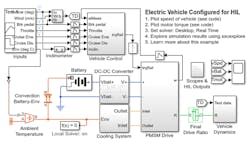
This EV model is for hardware-in-the-loop (HIL) deployment. Complete details of the test setup can be seen on the MathWorks website by clicking here. (Credit: MathWorks)
What portions of an EV drivetrain offer the biggest opportunities for efficiency improvements using HIL? Please provide an example or two if at all possible.
One of the ways automotive test engineers use HIL to improve the drivetrain development cycle is to use the system as a virtual dynamometer (also known as a virtual dyno), which simulates the machine that they have traditionally used to test their motors without putting them in cars. The dynamometer and its virtual twin connect the test motor to a calibrated load and then run it at a series of specific speeds while taking precise measurements of how much torque the motor is applying at each test point.
In the virtual dyno, an inverter and motor are simulated on a real-time computer and the motor controller under development is connected to the outputs. This allows a significant portion of testing and calibration of the controller without access to all of the equipment required to do extensive dyno testing. The dyno test hardware is expensive and test time is limited, limiting testing capabilities for auto manufacturers. (For more on this, see “Designing a Torque Controller for a PMSM through Simulation on a Virtual Dynanometer.”)
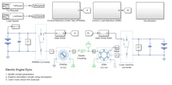
Shown is an example of a model of an EV dynamometer test. The test environment contains an asynchronous machine (ASM) and an interior permanent-magnet synchronous machine (IPMSM) connected back-to-back through a mechanical shaft. Both machines are fed by high-voltage batteries through controlled three-phase converters. The 164-kW ASM produces the load torque and the 35-kW IPMSM is the electric machine under test. The Control Machine Under Test (IPMSM) subsystem controls the torque of the IPMSM. The controller includes a multi-rate PI-based control structure. (Credit: MathWorks)
Current saturation is among the most important parameters that can be analyzed with a virtual dyno. As the current increases in a motor, the relationship between voltage and current moves from a linear relationship to a nonlinear relationship. Simple control methods that are efficient at low speeds become less effective as the current increases.
Implementing a flux weakening control addresses this issue, and not only improves motor efficiency, but also increases the maximum power at which a motor can operate when compared to traditional linear control techniques. HIL simulation can be used to fine-tune the flux-weakening algorithms to allow the motor to deliver the best possible efficiency and performance.
Are there any specific types of subtle interactions between mechanical, electronic, and electrical systems that HIL testing is particularly good at? An example or two would be wonderful!
Virtual dynamometers are also frequently used to analyze spatial harmonics that provide insights on how torque will be generated by a motor. Even under ideal conditions, the torque generated by an electric motor will exhibit some mechanical ripple, due to flexing of the rotor and other components under load.
A virtual dyno allows engineers to analyze the end-to-end behavior of the system and then see if the controller can be programmed to compensate for the ripple to produce a more consistent torque output. This kind of analysis is valuable in both EVs and PHEVs where it can improve operation and user feel, as well as enhance the lifetime of the electric drivetrain.
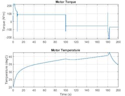
The plots represent outputs from the HIL test setup in Fig. 3. They show the torque produced by the PMSM motor in the electric vehicle and its temperature. During the first half of the simulation, the motor accelerates the vehicle to the commanded speed and then continues to apply torque to push the vehicle up a hill. During the second half of the simulation, the motor acts as a generator, as shown by the change in sign of motor torque. (Credit: MathWorks)
HIL simulation has also become a go-to tool for simulating the large, complex battery systems used in electrified transportation systems. It can be used for modeling and analyzing the behavior of individual cells as well as the entire battery subsystem. Looking at individual cells or groups of cells enables designers to gain insights into issues like cell balancing. Exercising a detailed model of the complete battery pack across a broad range of operating conditions enables a rigorous system-level analysis.
This type of simulation can be extremely valuable since batteries have a variety of states that are hard to recreate in real-world testing. For example, batteries are very sensitive to thermal effects, induced by both the ambient environment and the self-heating they experience during charge and discharge. As a result, it's necessary to test a battery pack across a large matrix of specific temperatures and states of charge. Running this series of tests in the "real world" requires expensive equipment and is very time-consuming.
In contrast, HIL simulation performed with an accurate model can be quickly configured and provide highly granular data in a matter of hours. HIL also greatly simplifies evaluating a vehicle's performance and behavior as its batteries degrade over time. The same model can be used to gain insights on efficiency and allows designers to explore various charging strategies.
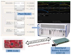
HIL testing of battery-management-system software is performed. The plant model (battery pack, contactor, inverter, charger) is modeled in Simulink. Code is generated and deployed to run on a Speedgoat real-time machine with battery emulator. (Copyright 1984–2020 The MathWorks, Inc.)
HIL also makes it much easier to perform the rigorous tradeoff studies involved with evaluating thermal-management strategies. A final, less obvious, issue is that batteries involve both electrical and chemical safety issues. As a result, testing them requires a lab setup that’s even more costly and challenging to operate as a workspace equipped to only deal with electrical safety issues.
This concludes the first part of the interview. In Part 2, MathWorks' Joel Van Sickel will take a closer look at implementing an HIL/CHIL system and some of the considerations involved with partitioning the system's functions between hardware and software. He will also discuss how HIL/CHIL testing helps designers improve the efficiency of their vehicle.
About the Author
Lee Goldberg
Contributing Editor
Lee Goldberg is a self-identified “Recovering Engineer,” Maker/Hacker, Green-Tech Maven, Aviator, Gadfly, and Geek Dad. He spent the first 18 years of his career helping design microprocessors, embedded systems, renewable energy applications, and the occasional interplanetary spacecraft. After trading his ‘scope and soldering iron for a keyboard and a second career as a tech journalist, he’s spent the next two decades at several print and online engineering publications.
Lee’s current focus is power electronics, especially the technologies involved with energy efficiency, energy management, and renewable energy. This dovetails with his coverage of sustainable technologies and various environmental and social issues within the engineering community that he began in 1996. Lee also covers 3D printers, open-source hardware, and other Maker/Hacker technologies.
Lee holds a BSEE in Electrical Engineering from Thomas Edison College, and participated in a colloquium on technology, society, and the environment at Goddard College’s Institute for Social Ecology. His book, “Green Electronics/Green Bottom Line - A Commonsense Guide To Environmentally Responsible Engineering and Management,” was published by Newnes Press.
Lee, his wife Catherine, and his daughter Anwyn currently reside in the outskirts of Princeton N.J., where they masquerade as a typical suburban family.
Lee also writes the regular PowerBites series.
