Conducting E-Band-Based Auto Radar Emblem Tests in Production Settings
What you’ll learn:
- How automotive emblems and bumpers affect antenna performance and measurements.
- Different types of radar systems.
- The best test setup for making E-band measurements.
The growing demand for advanced automotive safety systems, such as automatic emergency braking, blind-spot detection, lane-change assist, and adaptive cruise control, has led to ever-expanding array of radar system designs. Radar systems have proven inherent advantages for these environments, including better distance resolution, detection of more objects, and easy incorporation into automobiles.
Typically, a radar is placed behind a car emblem or bumper. Radar-system engineers must account for this factor, as the materials and coatings of emblems and bumper skins can interfere with the signals and pose a danger to drivers, passengers, and pedestrians.
To ensure most modern radar systems operate according to specification in real-world environments, engineers must measure material characteristics in the E-band frequency range (60 to 90 GHz). In the lab, high-end vector network analyzers (VNAs) are the instrument of choice.
A more time- and cost-efficient solution, though, is necessary for the production floor. A VNA that’s virtually “plug-and-play,” with fast and accurate calibration methods plus repeatable, easy-to-perform measurement capabilities, is optimum to test different materials, paint coatings, plastic injection methods, and material widths to accurately characterize their behavior.
The Impact of Emblems and Bumpers
Many automotive designs place radar systems in an unobtrusive location to protect and hide the car radar antennas. Often, they’re behind the automaker’s emblem or car bumper, which also serves as a radome. The dielectric materials from which emblems, bumpers, and even paint are made can adversely impact an antenna’s performance. Therefore, engineers must understand and account for the attenuating and reflective effects of those materials in designing and testing radomes.
The reason is physics. When a wave propagates through dielectric material, it will lose some energy. Ideally, radomes used for communications are made using low-loss dielectric materials. Any signal loss can be critical for a radar system used in a mission-critical automotive application. A measure of power loss in dielectric material to total power transmitted through the dielectric is called the loss tangent, which quantifies a dielectric material’s inherent dissipation of electromagnetic energy.
The signal loss caused by a radome reduces both the power transmitted out toward the target and the power received by the radar system reflected back from the target. The amount of radome signal attenuation directly affects the distance at which a target can be detected.
Understanding Radar Technology
Radar systems typically fall into three categories:
- Short-range radar (SRR) and Ultra-wideband SRR (UWB SRR): SRR and UWB SRR systems, with a shorter range of 0.5 to 30 meters, are more typically used in advanced driver-assistance systems (ADAS). These radar systems began in the 21.65- to 26.65-GHz frequency range, but they have already migrated to 77 to 81 GHz in Europe and will do the same in the U.S. by 2021. This frequency change will affect the mounting of SRR and UWB SRR sensors on the car chassis.
- Long-range radar (LRR): Typically, the LRR system is designed for an angular range of up to ±10° and a distance of 10 to 150 meters, which enables the adjustment of the automobile’s velocity between 20 MPH to 110 MPH.
In almost all adaptive-cruise-control (ACC) systems, a 77-GHz LRR system is used and typically mounted behind the car emblem. Transmit and receive patch antennas of the radar system are focused by a dielectric lens and operate at a 4-mm wavelength range. The radar beam is exposed twice to the influence of the radome. The first time is as it transmits through the car emblem towards the target and a second time is when the reflected signal returns from the target. While the principle of radar distance measurement seems intuitively simple, the requirements for automation and safety are enormous.
An LRR system uses frequency-modulated continuous-wave (FMCW) technology. It’s preferred because it measures the distance of other vehicles, as well as the speed of those automobiles.
When using an FMCW radar for distance measurements, the output signal frequency continuously changes over the transmission time, usually around 76 to 77 GHz, and it’s linearly modulated to reach a maximum of 81 GHz over a given time period. This waveform is called a chirp. Every frame consists of a designated number of chirps, each lasting for a given time (TChirp). The bandwidth and slope of each chirp are crucial to the FMCW radar’s performance. These parameters have a direct influence on the maximum range, maximum velocity, and their corresponding resolutions.
Selecting the Best Test Solution
Traditional E-band measurement systems are too expensive and cumbersome for most production environments. A more logical solution is to leverage an easy-to-use VNA system that supports E-band frequencies, calibrates easily, and measures all S-parameters (S11, S12, S21, and S22) for quick characterization of material behavior.
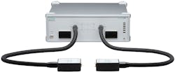
Another factor is the test configuration. Testing radome and bumper material is done through an over-the-air (OTA) setup with two antennas attached to the ports of a production-grade VNA (Fig. 1) to transmit and receive the signals. Antennas with the proper directivity and far-field characteristics must be chosen to match the requirements of the material under test (MUT).
The shape of the MUT must also be considered, as its width, paint, and manufacturing process can affect test results. Another question that needs to be answered is whether a single, large beam testing the entire surface is better than conducting multiple tests using a smaller beam. This depends on the size and uniformity of the material sample being tested.
It’s important to note the radiation environment when characterizing a MUT. The most important issue is reflections. If an open test environment is used, reflections may occur and cause inaccurate results. Reflections can be avoided by using one of two options. The first requires placing an absorbent material all around the room; however, this can complicate the setup. The second is to use the gating process available in certain VNAs.
As with most VNA use cases, measuring automotive radar systems requires proper configuration and calibration to achieve accurate results. A typical calibration method employed for these radiated measurements is the Line, Reflect, and Match (LRM) algorithm, in which a reflection plane is applied for reflective calibration, a line for transmission calibration, and an excellent match for load calibration.
The calibration standards for the LRM calibration are relatively easy to produce. For the LRM Reflection standard, both ports are measured with a metal plate placed perpendicular to each respective antenna. The Line standard is done with the two antennas transmitting to each other without the plate in between. For the Match standard, the metal plate is placed at a 45-degree angle to the antennas so that there’s minimal reflection to any port to achieve the same behavior as an excellent match. In this case, the use of an absorbent material placed to both sides of the metal plate can improve calibration.
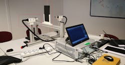
Figure 2 shows a test configuration in which the system holds the VNA extender heads with the antennas and the sample to be measured. The metal plate for calibration also is included.
Measurement Considerations
When conducting measurements, the bumper (or material sample) is set at the reference plane, which is the middle point between the antennas. When measuring bumper parts, mechanical positioners play an important role in precisely positioning the bumper to be measured.
The distance between the antennas depends on the test requirements. Far-field conditions need to be met, which is relatively easy at high E-band frequencies. At 75 GHz, far-field conditions are met roughly at 4 cm of separation from the antenna. It’s also important that the radiation spot on the sample not exceed or even be similar to the sample size to avoid dispersion. Figure 3 illustrates the situation if a dielectric antenna and horn antenna are used.
A high-gain dielectric antenna offers very high performance and narrow beam width. Using dielectric antennas with a distance of 31 cm between them, the radiation spot (diameter) is less than 3 cm for a 3-dB attenuation (less than 5 cm for a 10 dB attenuation). Similar calculations with the horn antennas show a spot of 57 mm in diameter. Based on these factors, a sample of 15 × 15 cm provides enough margin to be sure the spot will fall entirely in the sample.
When absorbent material isn’t available for use around the test setup, a measurement can be time-gated to improve the measurement and avoid external reflections that can appear in the trace as additional ripple. The material position serves as the reference plane and is considered “zero position.” The gating should be configured around the zero position.
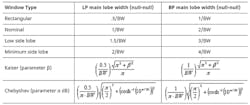
For accurate measurement results, the width of the time-gating window needs to be determined. It depends on the frequency span being used in the measurement (the higher the frequency span, the shorter the window size). The table below shows the relationship between the configured frequency span and the window size.
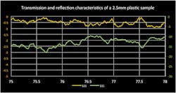
These values state the window size for reflection measurements. For transmission measurements, the window size must be doubled. Figure 4 is a display of a material sample measurement after the calibration and time gating is applied.
Conclusion
Automotive radar systems are becoming more prominent in mission-critical use cases. To ensure these systems perform according to specifications, engineers must conduct materials measurements on emblems and bumpers that are serving as radomes. A VNA that’s easy to use and can conduct measurements quickly addresses the needs to verify these designs during production.
