EMI and New-Generation mGig Ethernet Links
This article is part of the TechXchange: Delving into EMI, EMC and Noise
What you'll learn:
- What is mGig?
- Why is EMI such a threat to mGig transceivers?
- The three algorithms that can help mitigate EMI.
In the past, enterprise networks used 1000BASE-T Ethernet at the access layer for 1 Gb/s connectivity. But the advent of Wi-Fi 6 (IEEE 802.11ax) wireless access points has triggered a dire need for faster uplink rates between those access points and wiring closet switches. Other data-intensive use cases for enterprise campuses, university research, medical imaging, CAD/CAM, and media editing also require networking rates faster than 1 Gb/s.
As a result, the IEEE specified a new transceiver technology under the auspices of the 802.3bz standard, which addresses these needs. The industry adopted the nickname “mGig,” or multi-Gigabit, to designate those physical-layer (PHY) devices that conform to 802.3bz (capable of 2.5 Gb/s and 5 Gb/s) and 802.3an (10 Gb/s).
In addition to the Wi-Fi 6 dynamic, the pandemic has highlighted the need for more robust data rates to residential environments (for stay-at-home workers). Next-generation Internet Access systems such as 5G fixed wireless and 10G PON can satisfy those demands. But customer premises equipment (CPE) for these systems requires mGig technology to fully utilize the greater-than-1-Gb/s data rates offered by these new residential connectivity solutions.
The proliferation of mGig transceivers, which provide Ethernet connectivity with data rates beyond 1 Gb/s over unshielded copper wires, has brought with it a new danger: interference from radio-frequency emitters that can distort and degrade data-transmission fidelity. Why? Because unshielded cable acts as a giant antenna, picking up all sorts of stray electromagnetic interference (EMI).
The electronics industry has come up with several sophisticated digital-signal-processing (DSP) algorithms to contend with this problem. This article examines the most popular ones, how they work, and weighs which algorithms are better than the others.
EMI Mitigation—Why?
Enterprise Ethernet cables are typically Cat5e or Cat6 cables that contain four twisted-wire pairs encapsulated by plastic cladding. Higher-grade cables found in enterprise data centers, so-called Cat6a cables, are specified to higher bandwidth but are essentially similar in construction.
The key characteristic of all those cable types is that they’re unshielded and, as such, susceptible to EMI from a variety of RF emitters. Structured wiring rules allow for the installation of lengths of up to 100 meters of such cables. And, indeed, IEEE-compliant Ethernet transceivers are specified to support such lengths. But long rungs of such unshielded cable essentially form an antenna-like structure that picks up RF energy.
Pick-up of these interfering signals causes bit errors in Ethernet transmission and results in errored Ethernet packets. Some protocols are tolerant of such packet errors, as higher layers of the communications stack can detect and retransmit errored packets. But for many more modern applications, such as video or audio transmission, clock distribution, or preemptive packets with a high QoS priority, there’s no time to retransmit errored packets—and the result is more noticeable and potentially catastrophic.
One piece of good news is that many common RF emitters, such as cellular telephones, Bluetooth transmitters, Wi-Fi routers, and microwave ovens, emit frequencies that are in the 2- to 5-GHz range. Therefore, they fall outside of the mGig band of interest (0 to 400 MHz). But some RF emitters transmit directly in that band. Emitters such as FRS radios (walkie-talkies), AM and FM radio, TV, amateur-band (ham) radios, and police and taxicab radios are but a few examples.
One particularly insidious property of such RF emitters is that they can reside in mobile platforms, so their impact can be intermittent and hard to diagnose. A police car drives by, creates havoc with the network, and then leaves the IT manager to figure out what the heck happened.
Testing for EMI Susceptibility
In recognition of the hazard that EMI can unleash on Ethernet networks, the electronics industry has come up with a few documented, standardized tests that Ethernet networking equipment can be measured against to quantify their EMI susceptibility. The relevant EMI tests are:
- Telcordia GR1089
- IEC 61000-4-3 CISPR 24 for Radiated Susceptibility
- IEC 61000-4-6 CISPR 24 for Conducted Susceptibility
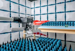
Radiated susceptibility testing is performed in an EMI test chamber (Fig. 1), where equipment is placed in an environment free of external interferers and calibrated RF energy is transmitted and swept throughout the band of interest. Without a doubt, testing in such a chamber is the “golden standard” and provides results that emulate real-life conditions in the best way.
However, gaining access to such a chamber can be cumbersome and pricey. For that reason, engineers have developed alternative equipment that can be used on a lab bench. Such equipment is typically realized with a clamping arrangement in which a length of unshielded cable is placed in an enclosure (clamp) and radiated with RF energy. The cable also is connected to a set of Ethernet transceivers. The test measures any disturbance the RF energy causes to data flow, usually by measuring the number of lost packets observed during the test.
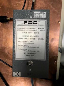
Because such clamps have trouble emulating the full spectrum of frequencies possible in the EMI chamber, testing has been divided into two types depending on the frequency band. Type 1, for low frequencies, is called Conducted Susceptibility (CS) testing and is typically implemented with a so-called coupling/decoupling network, or CDN (Fig. 2). Type 2 uses a cable clamp for equivalent radiated susceptibility (RS) testing (Fig. 3).
Field strengths between 3 and 10 V/m are typically used in EMI test chambers. However, tests up to 6 V/m are sufficient for the lab-bench tests due to the proximity of the RF emitter to the cable under test.
EMI Mitigation Algorithms
To contend with the problem of narrowband electromagnetic interference in Ethernet transmission systems employing unshielded twisted-pair cable, three types of EMI mitigation algorithms have been developed. These are typically implemented inside of the Ethernet transceiver silicon by using the device DSP engine.
The first of these algorithms, standardized by the IEEE under the auspices of the 802.3az working group, is called “Fast Retrain.” In this scheme, the link partner receiver is responsible for identifying the RF interferer. It then sends the interferer frequency information to the transmitter on the other side of the link. The transmitter, in turn, places a notch filter in transmit path, thereby eliminating transmission in the band dominated by the source of interference. Several such notch filters can be placed simultaneously to contend with a multiplicity of RF sources. The response time of this algorithm is in the 30-ms range.
Cisco Systems also created a similar algorithm it calls “Negotiated Fast Retrain,” and it’s published in the company’s ENG-977716 bulletin. The algorithm works on the same principles described for the IEEE standardized Fast Retrain scheme, but it has a response time between 30 and 200 ms depending on the link partner.
A third type of EMI mitigation system is called Common Mode Sense (CMS). The interesting property of this algorithm is that it only relies on the receiver electronics and doesn’t necessarily require cooperation with the link partner.
In the CMS scheme, the interfering signal, which is presented as a common-mode voltage on the link, is digitized, with a dedicated analog-to-digital converter (ADC) inside the transceiver silicon. Then it’s arithmetically subtracted from the incoming Ethernet signal using the transceiver’s DSP engine. Because this system doesn’t require communication between the two ends of the link, response times are relatively fast—on the order of 10 µs.
How Do These Algorithms Stack Up?
Comparing the effectiveness of these algorithms results in a predictable conclusion: Response speed is critical to maintaining a low packet-loss rate. That’s because during the time the transceiver is reacting to the onset of interferer energy, bit errors in the transmission occur and packets are lost. Figure 4 illustrates this concept by providing measured data between Fast Retrain and CMS systems. Here we see that the utilization of the CMS algorithm results in packet-loss rates that are several orders of magnitude better at both 3- and 10-V/m field strengths.
Note that the utilization of the CMS algorithm doesn’t preclude the use of the Fast Retrain algorithm as well. In fact, the CMS scheme is so fast, it can react during the time the Fast Retrain algorithm is being set up. And, in reality, modern implementations use both to enhance the device robustness to EMI.
Another method for comparing the effectiveness of CMS with other EMI mitigation algorithms involves laboratory measurements of transceiver devices that employ the CMS algorithm versus those that don’t use it.
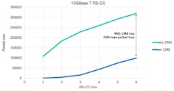
Figure 5 depicts the result of such a test for Radiated Susceptibility Equivalent with Cable Clamp (noted as RS-CC). Here, the IEC 61000-4-3 equivalent test was used, per CISPR 24. The test performs sweeps from 80 to 430 MHz in 1% steps with 1-second dwell per frequency. And equivalent RS test levels of 1 to 6 V/m are shown. As seen, a Marvell 10GBase-T transceiver with CMS tolerates 6X larger field strengths than one without CMS for equivalent packet loss.
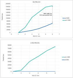
One might suspect that such results are pronounced because the data rate utilized—10 Gb/s—is quite high for a copper-based system. And the fact that lower data rates would, perhaps, demonstrate less dramatic results. However, that theory isn’t borne out with experimental data. As seen in Figure 6, data rates of 5 Gb/s and 2.5 Gb/s offer similarly impressive disparities between CMS and non-CMS transceivers.
Conclusion
mGig transceivers fill a growing requirement for higher-speed networking using incumbent unshielded twisted-pair copper cabling. However, their utilization of wider bandwidth and inherent noise sensitivity increases their susceptibility to interference from electromagnetic emitters. DSP-based mitigation algorithms, and the Common Mode Sense algorithm in particular, offer an effective technique to mitigate such susceptibility. They allow for error-free transmission in today’s modern enterprise, data center, and access networks.
Read more articles like this at the TechXchange: Delving into EMI, EMC and Noise


