A System-Component Approach to Functional Test Systems
Any programmable instrument can be used in a system. But what makes one system-ready and another just a programmable instrument?
When developing a functional test system from scratch, you have many choices of instruments, interfaces, and software. Good up-front planning can maximize throughput, minimize development time, and ease future expansion.
Maximizing throughput involves far more than simply choosing fast instruments. Minimizing development time goes beyond just selecting the latest software. And creating a system that can later accommodate more instruments, switches, or a bigger, power-hungry DUT without a complete redesign means more than an extra large chassis. Use of system components in your design can help to solve these problems.
A system component comprises a system-ready instrument, industry-standard software, and industry-stand-ard I/O. So, what makes one instrument system-ready and another just programmable? A system-ready instrument must have the following attributes:
• Usable speed. Fast I/O to the computer doesn t always translate into throughput.
• Ease of programming. If you have to dig out manuals and write your own drivers to interface an instrument to the computer, you re wasting precious time.
• Standard I/O. LAN and USB cables are available everywhere. Why resort to special cards for the PCI bus in your computer?
• System debugging capabilities. DMMs that don't require a PC to run them are less expensive and readily available so they can be put into service quickly.
• Built-in features. A simple digital-to-analog converter (DAC) can be turned into an arbitrary waveform generator (Arb) with software. But an instrument with standard waveforms and modulation capabilities built in saves time developing your test program.
• Universal AC power. If the instrument runs on AC, having one that can be used anywhere in the world without reconfiguring it for different line voltages or frequencies saves time and avoids searches for replacement fuses. If it's a card-cage instrument, having a card cage that runs on universal power also is essential.
• Remote support. A LAN-based instrument can be accessed from a Web browser anywhere in the world, allowing support personnel to help resolve problems quickly.
Industry-standard software is readily available and in use everywhere and has excellent support networks. This is especially true of Microsoft's Visual Studio.NET framework.
Industry-standard I/O consists of interfaces that have published specs, wide adop-tion, and ubiquitous availability. GPIB has served that need well but is fast being replaced by Ethernet and USB. FireWire is still a valid choice. All are recognized standards of IEEE.
To demonstrate the process of system-component-based design, let's follow a test engineer through the design of a system capable of testing the low-frequency, medium pin-count, medium-power modules common in the automotive and aerospace/defense industries.
Walk Through a Design
The first step in good system design is to devise an architecture that meets current needs with a reasonable way to extend the capabilities in the future. To maximize flexibility, the engineer chose an external PC rather than an embedded PC. He mixed modular instruments and rack-and-stack instruments, all with industry-standard interfaces. To handle future needs, he decided to leave 20% of the slots free or allow rack space for a bigger cage or additional instruments.
To avoid placing slow switches in a card cage designed for high-speed instruments, the engineer put switching in a separate subsystem. To minimize wire lengths and rack space, a mass interconnect was placed in front of the switching subsystem. Finally, to minimize development time, he developed applications with Visual Studio.NET with instrumentation extensions and standards-based drivers.
Once high-level architectural decisions were made, the engineer focused on the detailed instrumentation requirements for a specific DUT, in this case, an electronic throttle module with 14 pins on three connectors. According to the test spec, the following instrumentation was required:
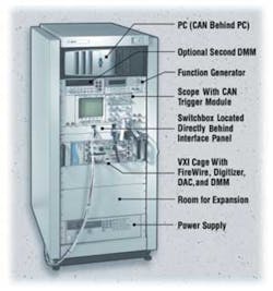
Programmable multimeter. Programmable power supply (0 to 13.5 V/0 to 10 A). Waveform generator capable of pulse width modulation, (0 to 10 VDC, 0 to 3 kHz). Voltage source (low-current 0 to 5 VDC). Waveform analyzer. CAN bus interface. Simulated or actual stepper motor load. Figure 1. Functional Test System for Examining Throttle Modules
The system houses a variety of rack-and-stack instruments along with some VXI-based units and a PC. The switchbox is located directly behind the interface panel in the center of the rack below the scope.
Given these parameters, the engineer examined various product offerings and chose those in Figure 1: a rack-mount Arb/function generator, a power supply, an oscilloscope with a CAN bus trigger module, and a dedicated switching card cage or switchbox. He also selected a four-slot VXI cage that contains a digitizer, a 16-channel DAC, and a high-speed DMM. An RS-232-C-based CAN interface was placed on a shelf behind the PC. A second DMM with a front panel was used during debug.
The system has four GPIB instruments: the power supply, a switchbox, a scope, and a DMM. A USB/GPIB converter was added so no PC slots would be required for a GPIB interface. FireWire was chosen to control the VXI instruments because it's a fast, industry-standard interface.
The Arb/function generator was connected to the PC's LAN using a crossover cable. Adding a hub or router would allow the system to handle more LAN-based instruments as they become available. The LAN provided an opportunity to use the instrument's built-in server to review and edit setup information remotely.
Connect Instruments Efficiently
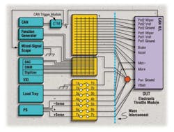
The next step was determining the best way to physically connect components in a way that allowed for future expansion. Figure 2 shows how they fit within the context of an overall switching subsystem.
Figure 2. Block Diagram of the Test System
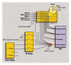
The star ground near the DUT helps eliminate ground loops and stray capacitance.
With the matrix, the engineer could connect any instrument to any DUT pin and easily add instruments. All connections to the DUT except for the CAN bus would be switched, making it possible to measure continuity from pin to pin.
In such complex setups, ground loops, sneak current paths, shorts, opens, signal loss, and stray capacitance are common problems. To combat these effects, two remedies were implemented.
First, a diagnostic test plan was written. Since the system was designed with a relay matrix, it was easy to route stimulus signals to measurement devices that verified the relays, cables, and instruments. A good system self-test can help uncover problem areas that prevent the right signal from getting to the instrument during development and after a system enters regular use.
Second, grounds from instruments, power, and safety devices were connected as closely as possible to the DUT's power ground in a star configuration that eliminates ground loops. Connecting grounds in this manner doesn t allow for continuity measurements between ground pins. The solution was to add relays to the ground pins as shown in Figure 3.
Figure 3. Star Ground With Switching Through General-Purpose Relays for Continuity Tests
The bold lines show the DMM path for a four-wire ohms measurement between the analog and digital ground.
A mass interconnect, or fixturing system, to the DUT is an option that any test engineer should carefully consider. It is tempting to omit it from a functional test system because the product changes so often and the extra time needed to rewire a fixture isn't productive. It's also not as likely that identical measurements on large numbers of devices will be required.
Simple clip leads might suffice, especially for small DUTs. However, several good reasons justify adding an interface panel. As stated by one design-verification (DV) engineer in the automotive industry: “First, it provides a physical location for us to mount interface components such as terminal blocks, fuses, and custom electronics between the system and the DUT. We can mount these components to the interface frame or to a shelf attached to the frame. Without the mass interconnect, we d need somewhere else to place these components.
“Second, with terminal blocks, we can easily modify wiring as the DUT changes and get convenient test connections during debugging. Finally, it provides a fast and robust means of changing connections to different DUTs using the same system.”
This DUT had only 14 pins, so the engineer decided that bringing these few pins directly out of the switchbox to DUT connectors would be sufficient. But to allow for possible addition of a mass interconnect, a feed-through panel located in front of the switchbox was provided.
The switching subsystem chosen has plug-in cards in the rear. For that reason, it was reverse-mounted in the rack so the cards faced the panel. This accomplished two goals: It minimized rack space because the switchbox and mass interconnect were in the same plane. It also reduced the wire length from the switching to the DUT, which decreased the possibility of stray noise pickup.
Switching Structure
The largest number of measurements or stimuli that must be applied at the same time for any given test helps determine the best switching structure. A four-wire bus was chosen because it allows four-wire resistance measurements on the DUT with a DMM.
By routing two matrix points, the Pot1 and Pot2 grounds in Figure 2, to the same pin on the DUT, the resistance measurement is very accurate because the remote sense location is at the DUT. If two wires aren t used, lower accuracy four-wire ohms measurements still are possible inside the relay matrix.
It's seldom necessary to have more than two isolated instruments or four single-ended instruments active at once because electronic modules usually contain built-in test routines that can exercise one function at a time. However, a fifth bus wire can be added to serve as a common reference for single-ended devices like the scope or floating devices that can connect to ground, such as the function generator or DMM. For that reason, the engineer chose a five-wire measurement bus.
Multiple signal sources can be connected to the same pin when using a matrix. It's important not to short such sources together accidentally. Experienced engineers carefully write switching routines to eliminate this possibility or offer warnings when such conditions occur.
However, it's wise not to rule out such conditions completely. There are times when it might be useful to allow the connection of two sources to the same pin, such as when the sources have their own output disconnect relays or when paralleled sources are desired.
This DUT had self-test capabilities that could be activated over the CAN interface. A command could, for instance, tell the internal processor to measure a voltage fed to the Pot1 Wiper input from the DAC. This not only tests the wiper pin but also the capability of the internal processor to correctly measure pin voltages.
Special care was required when using the scope. As a ground-referenced device, it requires that the star ground be connected to chassis ground. A general-purpose relay handles this task (1a/1b in Figure 2).
In addition, the scope can t measure the stepper drive, which is a floating H-bridge circuit. It can measure Mot+ or Mot• with respect to ground but not Mot+ to Mot , so the system required an isolated digitizer.
Although 16 were available, Figure 2 shows only one DAC channel connected to the matrix. It's more typical to run all DAC lines to the mass interconnect so they can be connected to various DUT pins in the fixture.
This approach removes the flexibility of routing a DAC to any pin programmatically. If more simultaneous DAC signals are required and it's not desired to permanently assign them to DUT pins, you can feed them into an expanded matrix using more rows.
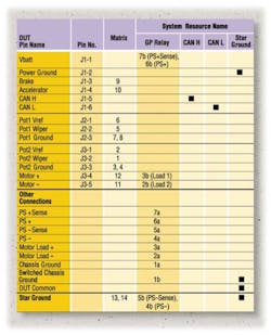
The engineer made a wiring map that shows how the DUT connects to the system. A spreadsheet with DUT pins as rows and system resources as columns is a handy way to accomplish this. Figure 4 shows one for this test system. When it's necessary to test a different DUT, the test engineer simply would create a new spreadsheet and wire a new fixture accordingly.
Take Advantage of Drivers
Combining so many interfaces presents a programming challenge. By using Visual Studio.NET with specialized instrument libraries, a control program can easily communicate with instruments of all types. Several drivers that run under VS.NET are available.
Specifically, the Interchangeable Virtual Instruments (IVI) Foundation has sponsored the development of IVI-COM, a driver architecture based on Microsoft's Component Object Model (COM) standard. Also required are controller-independent software modules as defined by the VXIplug&play Systems Alliance including the VXIplug&play drivers and the underlying Virtual Instrument Software Architecture (VISA) I/O libraries. With these drivers, the engineer can create an application with a high degree of hardware independence. In fact, should an instrument's I/O interface change (for example, if shifting a unit from USB to LAN), all that must change is the instrument's initialization string.
In addition, combining VXIplug&play and IVI-COM drivers with Microsoft's IntelliSense functionality in the VS.NET environment can ease the task of figuring out the optimal commands to get the best setup consistent with the required speed, accuracy, and resolution. Using IntelliSense, a user types an instrument's symbolic name, such as MyHp34401, and a decimal point; then a menu pops up with all available instrument functions and their descriptions. If any parameters are required for a function, they appear along with their data types.
In design and DV environments, engineers use both graphical and text-based languages to develop tests. In manufacturing, the norm is a test executive in which engineers create sequences of prewritten tests in languages that can be a mixture of graphical and textual. This example uses Visual Basic and Visual C++. VS.NET provides a widely supported environment for test and GUI development that is rich in features and integrates well with instrumentation.
Conclusion
Designing a functional test system requires up-front planning to make it flexible, extensible, and fast. System-ready instruments, industry-standard software, and industry-standard I/O can streamline this process.
About the Author
Brian Wood has been with Hewlett-Packard and Agilent Technologies for 30 years. He has designed hardware, firmware, and software for in-circuit test systems and driver software for automotive functional test systems. He also served as an application engineer. Mr. Wood graduated with a B.S.E.E. from the University of Arizona. Agilent Technologies, Basic, Emerging, and Systems Technology Division, 815 W. 14th St. SW, Loveland, CO 80537, 970-679-2915, e-mail: [email protected].
FOR MORE INFORMATION
on building a functional test system
www.rsleads.com/404ee-200
Seven Steps to a
Fast Measurement System
1. Choose Fast Instruments Wisely
Look hard at instrument specs. Often, measurement speed is based on reading thousands of samples. But in functional test, it's more common to connect a DUT pin to a measurement device, take a single measurement, open the relays, and repeat on a different pin. In such a case, the dramatically slower single-sample speed of a DMM is far more important. At resolutions of 5.5 and 6.5 digits, single readings are somewhat faster with PXI DMMs than GPIB units.
The fastest reading speed is obtained with 4.5-digit resolution. In this case, PXI and GPIB DMMs are comparable in throughput, on the order of 130 readings/s not including switching time. However, when switching time is included, the total speed for both types of DMMs at any resolution generally is <10 readings/s. In a functional test system, you must pay attention to realistically attainable measurement speeds.
2. Minimize Instrument State Changes
Voltage, current, and resistance measurements are so common that manufacturers have worked to make them as fast as possible. Even so, random range and function changes can interfere with fast tests.
To compensate, set up tests so AC and DC readings on one instrument aren t intermixed. Also, try to select and stay on a range that gives the needed resolution for most measurements.
Finally, set autozero to once or off. The execution time of one manufacturing production test program improved from 90 s to 60 s merely by changing autozero from on to once. But if the system's temperature drift is more than minimal, perform an autozero periodically.
3. Use Fast I/O
Is it really true that GPIB is slow and LAN is fast? Tests indicate that the overhead of the layers of LAN and VISA actually makes LAN slower than or comparable to GPIB unless the system is transferring considerable data. However, LAN-based instruments have built-in Web servers that can make setup and remote operation easier.
As LAN speeds increase, that technology should easily win the speed wars, but GPIB will continue to be viable for some time to come. USB/GPIB converters and LAN/GPIB converters are available to eliminate a PCI card in your PC. Although there is a slight speed penalty, it is not perceptible for many applications.
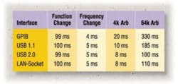
FireWire is about four times faster than a 100-Mb/s LAN so it's the best choice today for an industry-standard connection to VXI. Table 1 shows the relative speeds for various operations for a stimulus instrument having GPIB, USB, and LAN interfaces. The instrument's internal speed clearly dominates setup changes, making I/O choices seem moot. But download speeds get much better with LAN and USB when large amounts of data are involved.
4. Use Relays Wisely
Reed relays are excellent when connecting measurement instruments and low-current stimuli to a DUT. They re fast, typically 0.5 to 1.0 ms, although they can have a higher thermal offset voltage than armature relays so it is important to pay attention to required accuracy. Armature relays typically switch in 10 to 20 ms so use them for higher current loads and group tests so they can stay connected as long as possible.
5. Use the Right Instrument for the Job
Scopes are slow and generally have 8-b resolution but high bandwidth and a built-in display. Digitizers acquire data quickly at 14-b resolution but don't have a display. Each has its own usefulness.
Other instruments, such as DMMs and power supplies, can serve as low-frequency digitizers in a pinch. For R&D and DV, a scope is desirable, especially for debugging purposes. Scopes don't require a trigger and can show when a desired signal is not present. Digitizers require a trigger, and it can be a nuisance to figure out the correct settings unless you can see if the waveform actually is making it to the instrument. As a suggestion, use both instruments during system development but only the faster one in the final system.
6. Don t Program Carelessly With Timing Delays
The delay statement is likely the most misused in all of test programming. A slow program is bound to have many seconds of delays. It's natural for test programmers to insert delays during debug, but many don't remove them once they get a test working.
Most instruments have triggering systems or at least can programmatically announce when they are done. Use these features instead of randomly tacking delays into a test routine.
7. In Production, Move Repeatedly Failing Tests to the Front
If a DUT exhibits consistent problems, why test the entire DUT? A system should find a DUT destined to fail as soon as possible. To allow them to be moved around as needed, it helps a great deal to organize your test program so tests can be run without depending on prior setups.
All contents • 2004 Nelson Publishing Inc.
No reprint, distribution, or reuse in any medium is permitted
without the express written consent of the publisher.

